A long time ago for a product, I worked out this issue by using a current mirror. Basically, I used a matched NPN pair wired up as a mirror and sent a very small (tens of microamps) current to the LED, not enough to light it. The mirror output swung enough voltage that it could read it with a GPIO. Once my diags were done I turned off the current mirror so even the phantom sense wasn’t present. Why did I go to so much trouble? I was very short on GPIOs and needed to resort to some tricks to reuse them.
The ADC can measure the FET drain voltage with the FET ‘off’, with a bit of work. First, toggle the FET 'on' then 'off' to discharge the drain and trace capacitance, then quickly sense the drain voltage afterward. The voltage will stay at 0 if the LED is unconnected, or drift up towards Vcc with the LED present as the LED leakage bleeds off charge.
That said, the ADC sensing method poses a couple of difficulties: ADC input range (which needs to include Vcc), and ADC input impedance loading the circuit when the driver FET is 'off'. Either one will prevent proper sensing of the FET drain charge.
What to do then? Forget the ADC. There's an easier way.
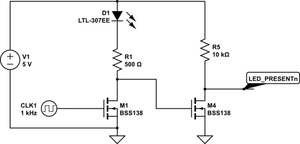
Use an nFET to watch the driver drain voltage. Just like with the ADC method: pulse the driver 'on' then check the FET state shortly afterward. If the sense FET stays off, no LED; if it turns on, LED is connected. Try it, here:
<!-- Begin schematic: In order to preserve an editable schematic, please
don't edit this section directly.
Click the "edit" link below the image in the preview instead. -->

<!-- End schematic -->
This circuit takes advantage of the fact that there's a bit of capacitance present on the driver FET drain and the board trace. The sensing nFET doesn't load this, and so can detect the driver drain off-state charge with the LED present or absent.