I think you're mixing up a few different concepts. Let's tackle them one at a time.
First, the output voltage of an op amp is indeed \$V_{out} = A_v \cdot (V_+ - V_-)\$. That's the definition of a differential amplifier. But in an op amp, \$A_v\$ is huge -- a million or more in some cases. Because of that, any negative feedback causes the op amp inputs to be very close to each other. This is the only condition that gives you a non-huge output voltage.
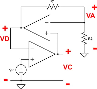
As for your complex circuit, there's no voltage source driving an op amp output. The middle op amp is acting as a non-inverting amplifier. The input is \$V_C\$ (the output of the bottom op amp) and the output is \$V_D\$. The relationship between them is:
$$V_D = V_C(1 + \frac {R_1}{R_2})$$
\$R_1\$ and \$R_2\$ form a voltage divider between \$V_D\$ and ground, with \$V_A\$ in the middle. The relationship is:
$$V_A = V_D \frac {R_2}{R_2 + R_1}$$
We know that \$V_D = V_{in}\$ and \$V_C = V_A\$. So what does that get us?
$$V_A = V_{in} \frac {R_2}{R_2 + R_1}$$
The bottom two op amps form a non-inverting attenuator -- an amplifier with a gain less than one. The output is \$V_A\$. This feeds into the top op amp, which acts as a non-inverting amplifier.
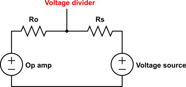
To answer your first question -- if you connect an ideal voltage source to an ideal op amp output, you break the rules of circuit theory and don't get a meaningful answer. In real life, what happens depends on how the voltage source and op amp are built. Probably it will be something like this:
<!-- Begin schematic: In order to preserve an editable schematic, please
don't edit this section directly.
Click the "edit" link below the image in the preview instead. -->
<!-- End schematic -->
The output resistances of the op amp and voltage source will form a voltage divider between the two. These resistances will be small (and unpredictable), so lots of current will flow and you won't know what the voltage will be until you try it. Obviously, this is bad, so don't do it. :-)
**UPDATE:** Why is \$V_C\$ affected by \$V_D\$? Because \$V_D\$ is one of the inputs to the bottom op amp. Maybe you're confused because this seems like circular reasoning -- \$V_C\$ controls \$V_D\$, but \$V_D\$ also controls \$V_C\$. So how does \$V_C\$ "know" where to go if it doesn't know what \$V_D\$ is yet?
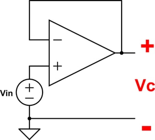
To improve your intuition, it might help to start with some simpler examples. Consider the basic voltage follower:
<!-- Begin schematic: In order to preserve an editable schematic, please
don't edit this section directly.
Click the "edit" link below the image in the preview instead. -->
<!-- End schematic -->
Imagine this circuit with \$V_{in}\$ powered off. \$V_{in}\$ and \$V_C\$ are both 0V. Now we turn on \$V_{in}\$. The non-inverting input's voltage becomes greater than the inverting input's voltage (\$V_+ > V_-\$). Because of the op amp's huge gain, the output shoots up. But the output is connected to the inverting input, so when it rises above \$V_{in}\$, you get \$V_- > V_+\$. This causes the output go to down again. So when the output is greater than the input voltage, it drops. When the output is less than the input voltage, it rises. The only stable state is when the output is (almost) equal to the input voltage.
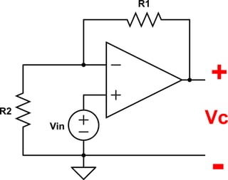
Now let's add some resistors:
<!-- Begin schematic: In order to preserve an editable schematic, please
don't edit this section directly.
Click the "edit" link below the image in the preview instead. -->
<!-- End schematic -->
This is a non-inverting amplifier. It works the same way as the voltage follower, but now the output has to be higher than \$V_{in}\$ to stabilize. (The stable state is really when \$V_- = V_{in}\$.) But adding resistors doesn't change the basic principle, right?
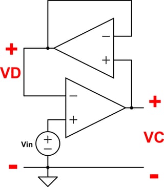
Now try this. Here's a really dumb voltage follower:
<!-- Begin schematic: In order to preserve an editable schematic, please
don't edit this section directly.
Click the "edit" link below the image in the preview instead. -->
<!-- End schematic -->
This looks complicated, but it really doesn't change anything. The bottom op amp's output rises, which causes the top op amp's output to rise. When the top op amp's output goes above \$V_{in}\$, the bottom op amp's output starts to fall, which makes the top op amp's output fall. The only stable state is where both op amp's outputs equal \$V_{in}\$.
Your circuit is like that, only the top op amp forms a non-inverting amplifier instead of a voltage follower:
<!-- Begin schematic: In order to preserve an editable schematic, please
don't edit this section directly.
Click the "edit" link below the image in the preview instead. -->
<!-- End schematic -->
This is the same as the previous circuit, except now the bottom op amp's output has to be less than \$V_{in}\$ for the circuit to stabilize. For example, if both resistors are 1k, then:
$$V_D = V_{in}$$
$$V_A = V_C = \frac 1 2 V_{in}$$
Try changing any of those voltages and you'll have a voltage difference between the op amp inputs. For example, if the bottom op amp's output (\$V_C\$) goes up, the top op amp's output has to rise, because \$V_C > V_A\$. But that would make \$V_D > V_{in}\$, which means the bottom op amp's output has to fall again.
This concept of connecting an output back to an input is called negative feedback. It's widely used in electronics and mechanical control systems (among other things). There's a whole subfield of engineering called Control Systems that studies how to use negative feedback to improve the performance of a system and how to guarantee that it doesn't become unstable.
I found the ideal op amp rules very confusing when I first learned them. Hopefully these examples of transient behavior will help you make sense of things.