2
\$\begingroup\$

I want to build a weight scale with 0.1 gram resolution. But I have some problems in my initial stage.

I am using a load cell with sensitivity of 1mV/V and excitation voltage of 3 V.

  1. With no weight, the load cell output shows -0.089 mV and with full load (500gms) it shows 2.895 mV. Is -0.089 mV the noise of my load cell? If so, how could I solve this problem? Why is my load cell mot showing an output of 3mV for 3 V of supply?

  2. I have connected the load cell to IN amp (PMI AMP04FP) with a gain of 100, with no load, I get an output of 3.203 mV and with full load I am getting an output of 278 mV. Why is the IN amp showing an output of 3.203 mV? Is it the offset voltage? If so how could I solve the problem? Why am I getting 278mV instead of 300mV?

    I have gone through the basics. But couldn't get my mind clear because of a lot of information in a small time. I know that my questions are basic and need some reading. I would be glad if someone could explain me what is happening and how to proceed. I am willing to learn. So, any kind of help (links, books etc) is appreciated.
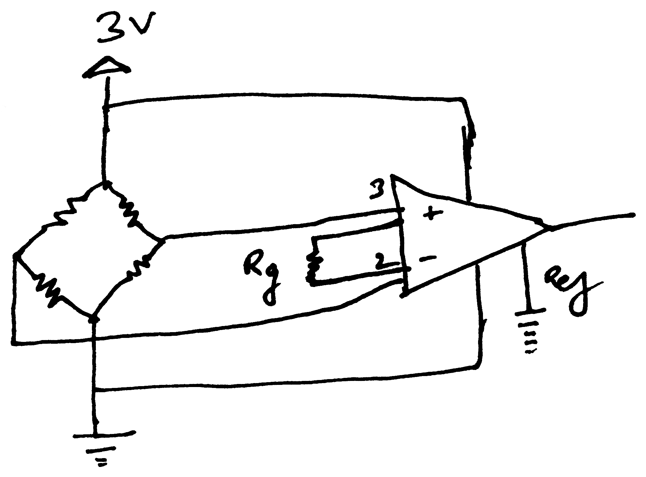
Schematic

\$\endgroup\$
1
  • \$\begingroup\$ You should really add a differential low pass filter between the load cell and instrumentation amplifier to prevent RF offset error. \$\endgroup\$
    – Matt Young
    Commented Aug 20, 2014 at 14:13

3 Answers 3

2
\$\begingroup\$

Presumably your sensitivity of 3mV/V is with a 500 gramme load. and given that there is a small offset of -0.089 mV and this rises thru zero mV to 2.895 mV, there is a change of 2.984 mV - that's quite close to 3mV and, as always with mechanical-electrical devices you need to make a calibration adjustment. In other words the sensitivity of the device is nominally 3 mV per volt and 2.984 mV represents a small (and acceptable) error of 0.53%.

An In-amp is also subject to errors both in gain and offset. 3.203 mV offset represents an input offset of 0.032mV. Realistically, the error from the in-amp is adding to the natural loadcell error of -0.089mV and making it +0.032mV i.e. the in-amp input offset error is 0.057mV.

The device you have chosen has a maximum input offset error of 0.3mV at ambient temperature conditions so this error is well within specification for the device.

As for the output not being 300mV but 278mV this is usually due to the tolerance on the resistor that sets the gain. It should be also noted that the gain accuracy for this device (assuming a perfect gain-set resistor) is +/-0.75%.

Other factors that can contribute to problems are layout, power supply levels, inaccuracies in your meter/measurement device etc...

\$\endgroup\$
0
\$\begingroup\$

This is your instrument amp? http://www.analog.com/static/imported-files/data_sheets/AMP04.pdf

I found the comma's in your numbers a bit confusing. I assume that 3,203 mV is what I would write as 3.203 mV.
So first there is some DC offset in the load cell. That's not surprising. (do you have a model number.) and for the second there is also a DC offset in your amp. The spec sheet says a max of 150 uV (x 100 gain) = 15mV. You see about 3 mV so that seem reasonable.

Then your full load number... why do you expect 300mV?
(sorry maybe this should be a comment?)

\$\endgroup\$
6
  • \$\begingroup\$ My load cell sensitivity is 1mv/v with supply of 3v. I would like to measure the voltage changes for 0.1 gram load. I couldnt see any changes in load cell output or even in Inamp output for this small weight changes. How could i do that. Is there anything to add in my circuit. Is it better to leave the ref pin to ground?? \$\endgroup\$
    – tony
    Commented Aug 20, 2014 at 14:10
  • \$\begingroup\$ OK if 500g gives you ~300mV then 0.1g = 0.06mV, 60uV. Is there enough resolution in your voltmeter to see that? (maybe five or six digits.) \$\endgroup\$ Commented Aug 20, 2014 at 14:34
  • \$\begingroup\$ yes, I have enough resolution. But, I couldnt see a change of 60uv in my DMM. Am i missing any connections in my circuit \$\endgroup\$
    – tony
    Commented Aug 20, 2014 at 15:05
  • \$\begingroup\$ Your circuit looks OK. (Well a lot of things could be done. I assume there are bypass caps on the power supply, and as Matt Young commented a little low pass filtering of the signal lines might help if noise in an issue.... what's the load cell impedance? (model number?)) Maybe the load cell is not so good up at the high end of it's range, try 100 grams, +/-0.1 grams. \$\endgroup\$ Commented Aug 20, 2014 at 15:46
  • \$\begingroup\$ @tony Since this is an English site, the decimal separator mark is the period (.) rather than the comma (,). See this meta question for more information. \$\endgroup\$
    – JYelton
    Commented Aug 20, 2014 at 16:55
0
\$\begingroup\$

Assuming that full scale is 500 g and you desire a 0.1 g resolution, I would go about as follows:

  • Determine the temperature range over which this should work. Let us pretend it is 25°C to 35°C.

  • So choose a sensor which is rated for 500 g and has low tempco for zero and span in the 25°C to 35°C range. Let this be 100 ppm for zero and 100 ppm for span.

  • The load sensors are never ideal and when you get a sensitivity of 1 mV per volt, it is just a nominal value. It need not be exactly 1.000 mV per 1 V or 3.000 mV for 3 V at 500 g.

  • Generally these sensors also have an initial offset which combines with the offset of the op amp, and that is why you presumably get -0.089 mV when no load is placed on the system. You need to adjust this offset and bring it to less than about 1 uV. the sensitivity of the sensor is the change in output when load is varied. So if you get, after amplification, 3.203 mV at 0 load and this changes to 278 mV at full load.
    Without sounding to be too technical (such as is this for 0.0 g to 500.0 g change?), the difference is
    \$278-3= 275 \text{ mV}\$
    for a change in load of 500 mV. This is called span and to get this to chnage to 300 mV, one has to trim the gain, make it a little higher.

In summary, do not expect the output of the sensor (or for that matter the output of an amplifier) to be 0 for 0 input (load). Nor would one get 300.0 mV with a gain of 100, since the 3 mV sensitivity claim is a nominal one. Then there is the drift of the amplifier and drift of "zero" and "span" of the sensor to be considered.

Best of luck.

\$\endgroup\$
1
  • \$\begingroup\$ This answer has good detail, but please try to use good spelling and grammar and format your answers to make them easy to read. There is lots of detail on the help pages or look at other people's answers. \$\endgroup\$
    – Xcodo
    Commented Jun 30, 2015 at 11:41

Your Answer

By clicking “Post Your Answer”, you agree to our terms of service and acknowledge you have read our privacy policy.

Not the answer you're looking for? Browse other questions tagged or ask your own question.