3
\$\begingroup\$

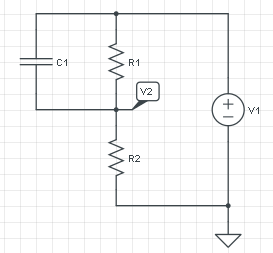
This is not homework. I have this circuit, and I want to calculate V2. I know it is equal to V1 at t=0, and equal to \$V1 \cdot \frac{R2}{R1+R2}\$ at t=\$\infty\$, but I don't know how to calculate the charging of the capacitor.

enter image description here

All I find on Google is charging of an RC, without the parallel resistor.

\$\endgroup\$
1

2 Answers 2

3
\$\begingroup\$

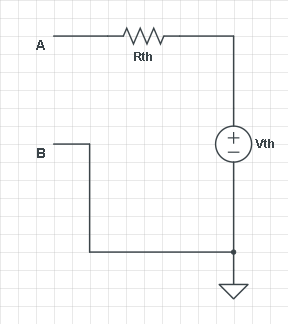
The answer is in Thévenin, like Alfred and jippie also suggested. Thévenin claims that any 1-port network consisting of voltage sources and resistors can be replaced by a voltage source and a series resistor across that port, and who am I not to believe him?

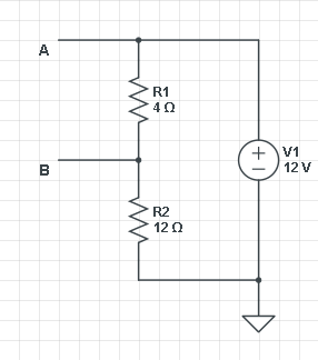
Let's consider your circuit without the capacitor and assign its connections as the circuit's port.
enter image description here enter image description here

First we look for \$V_{th}\$, which we do by leaving the output open-circuit, so that \$R_{th}\$ can't cause a voltage drop. Then R1 and R2 form a voltage divider with \$V_{AB}\$ = V1 \$\times\$ R1/(R1 + R2) = 3 V. (I'm using actual values for voltage and resistors to make it more graphic.) That's \$V_{th}\$. Fine.

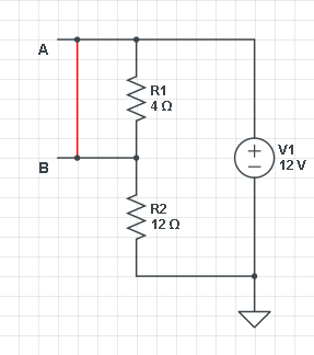
Next we have to find \$R_{th}\$. You can do that by shorting all voltage sources and measure the resistance between A and B. But let's do it the alternative way: short-circuit A to B, and measure the current through that point. That should be \$V_{th}/R_{th}\$. Both methods give the same result, and it depends on the kind of circuit which way is best.
enter image description here

So shorting A-B we get I = V1/R2 = 12 V/ 12 Ω = 1 A. (What a coincidence! :-)) Then \$R_{th}\$ = 3 V/ 1 A = 3 Ω. If we now reconnect our load we have the typical RC circuit where C1 is charged via a series resistor (let's say C1 is 1 F):

\$ V_C(t) = V_\infty + (V_0 - V_\infty) e^{\dfrac{-t}{RC}} \$

\$V_\infty\$ is \$V_{th}\$ because after C1 is charged there won't be a voltage drop across \$R_{th}\$. And \$V_0\$ is 0, we start with an uncharged capacitor. Then

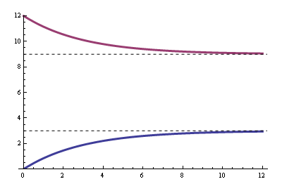
\$ V_C(t) = 3 V + (0 V - 3 V) e^{\dfrac{-t}{3 s}} =3 V (1 - e^{\dfrac{-t}{3 s}}) \$

And that's the well-known charging equation.
enter image description here

The blue curve is the voltage between A and B, the purple curve is the voltage at B with respect to ground.
\$\endgroup\$
3
  • \$\begingroup\$ Haha! Nicely explained and was really funny. I got a little lost when you have posted both the thevenin circuit and the original circuit without the capacitor, but then I recovered quickly. \$\endgroup\$ Commented Jul 9, 2012 at 21:40
  • 1
    \$\begingroup\$ @abdullah - Funny??? Not the exponential, I hope :-) \$\endgroup\$
    – stevenvh
    Commented Jul 10, 2012 at 4:15
  • \$\begingroup\$ lol. what happened to the exponential ? :) \$\endgroup\$ Commented Jul 10, 2012 at 6:44
4
\$\begingroup\$

There's always more than one approach to solving a circuit problem but the approach I generally find most useful in this type of problem is to find the Thevenin equivalent resistance \$R_{TH}\$ "seen" by the capacitor. This will allow you to find the time constant, \$\tau = R_{TH}C \$.

To find the Thevenin resistance, remove the capacitor and zero the voltage source (replace with wire). Now, find the resistance between the terminals where the capacitor connects; that resistance is \$R_{TH}\$

If you've already found the voltage across the capacitor at t = 0 and t = \$\infty\$, just "connect them together" with the exponential function:

\$v_C(t) = [v_C(\infty) - v_C(0)](1 - e^{t/\tau}) + v_C(0)\$

For \$v_C(0) = 0\$, this simplifies to:

\$v_C(t) = v_C(\infty)(1 - e^{t/\tau})\$

Now that you have \$ v_C(t)\$, you have \$v_2(t) = V_1 - v_C(t) \$

\$\endgroup\$

Your Answer

By clicking “Post Your Answer”, you agree to our terms of service and acknowledge you have read our privacy policy.

Not the answer you're looking for? Browse other questions tagged or ask your own question.