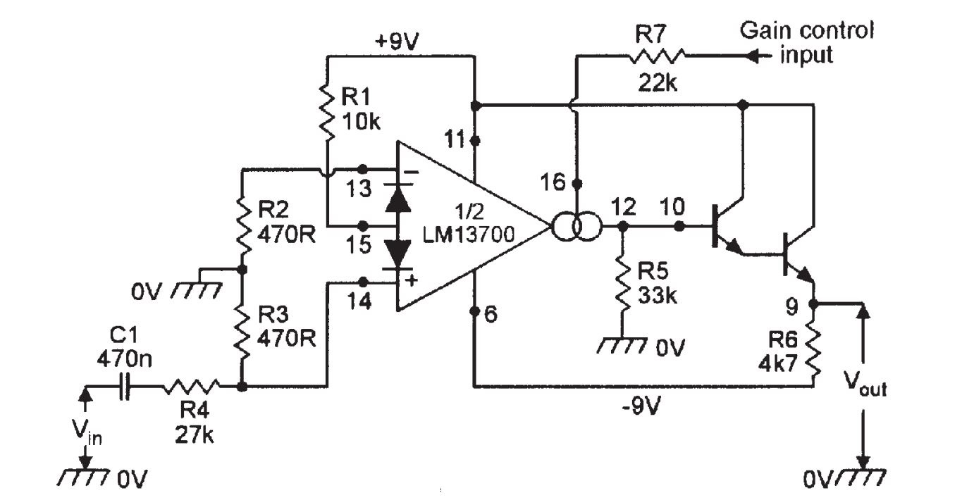
I'm trying to build the circuit shown below. This is a VCA, application taken from Nuts & Volts magazine I think (don't have the article). I know very little about OTAs in general but from what I could understand the limits of the control voltage are the supply voltages so the max control current is about 0.4mA. How can calculate the output from that given the circuit below and given a known input voltage? Also, would it be possible to supply control current via a lower voltage and smaller resistor?
1 Answer
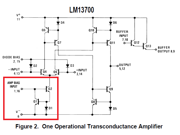
I've never used this device so I'm only answering half the question - the bit that relates to the gain control input. It's always worth a look in the data sheet. Here's what the equivalent circuit is: -
On pins 1 or 16 the maximum voltage can only be the Vbe of Q2 plus the diode drop of D1. This is going to be somewhere between 1V and 2V relative to the negative rail.
The resistor in series on your circuit is to attempt to convert a variable voltage to a variable current so yes, it is possible to deliver the variable constant current drive from a much lower voltage, probably from as low as 3.3 volts above the negative rail.
-
\$\begingroup\$ Thank you for that, does make sense. The bias input simply "sits" two "diode drops" from the negative rail. This also means I calculated the input bias the wrong way! It should be [Vcc + |Vee| - Vbe - Vf(d1)] / R7. I still to find out how to calculate gain. The output (before the buffer) is actually a current source so Z is very high. With a load resistor RL the max swing would be Ibias * RL (+/-). But the gain needs to be set not to exceed this - how can I do that? \$\endgroup\$ Commented Feb 25, 2015 at 11:45
-
\$\begingroup\$ I'm not sure - I saw the question and thought that I could help you with 50%. I've never used this device before so either you dig for this or I dig for this. Now lemme think, who is the best digger LOL! \$\endgroup\$– Andy akaCommented Feb 25, 2015 at 12:08