1
\$\begingroup\$

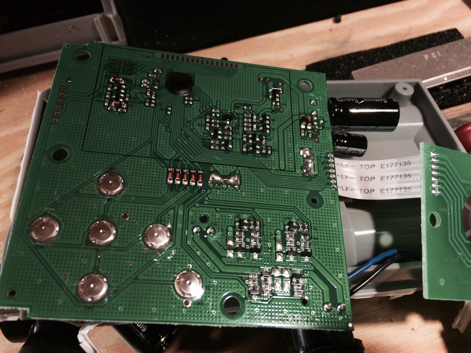
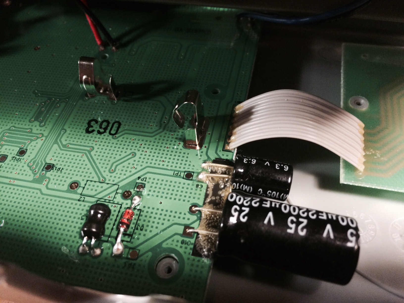
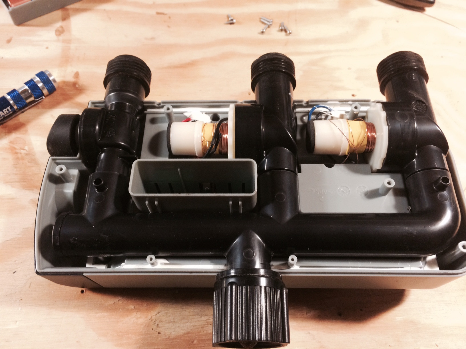
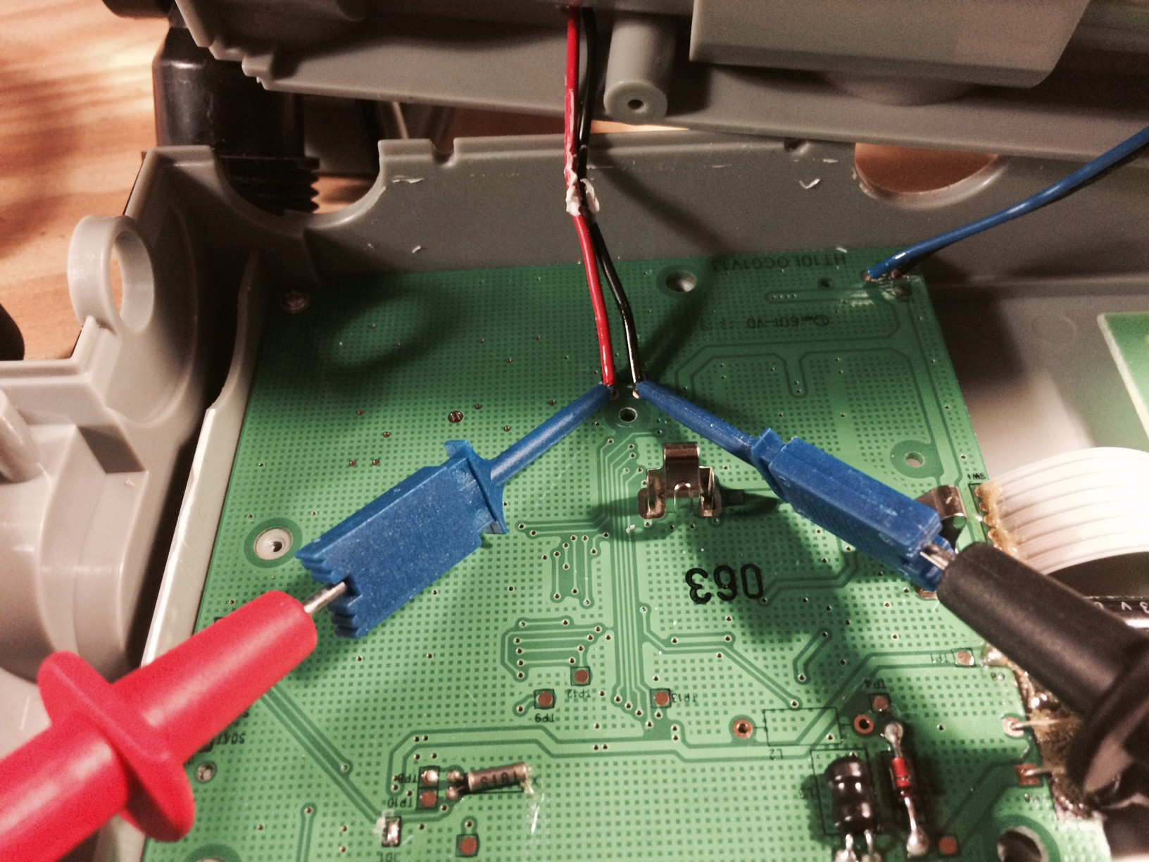
I have a automatic watering timer that I purchase from the internet. I'm attempting to hack it into something that I can either trigger from a micro-controller, or sense when the solenoid has been opened, and respond accordingly with the micro-controller. The unit runs on 2 AA batteries, so I'm assuming its 3V, there are a number of components and then 4 leads ( two for each solenoid ) that run to a coil. I tried measuring the voltage across the solenoid when the valve opens but the way the components are configured, it makes it impossible to power, control and measure it. I also wonder if the solenoids are solenoids all at or some other mechanism. I realize that my question is some what vague, but perhaps someone has had experience taking one of these garden watering timers apart and can give me some place to start.
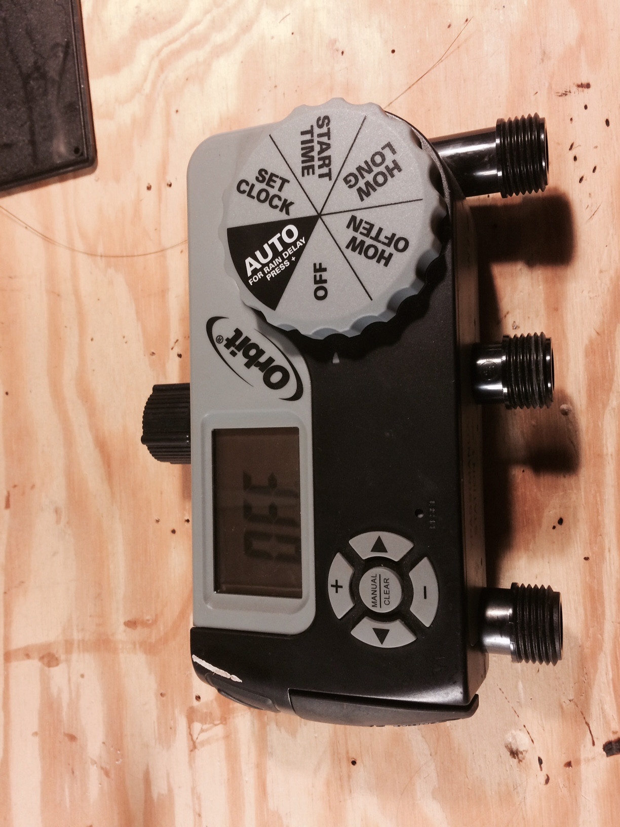
enter image description here enter image description here enter image description here enter image description here enter image description here

\$\endgroup\$
5
  • \$\begingroup\$ Is there a picture showing the valves? I'd bet a quarter that the valves aren't solenoids, but rather small motor operated valves. Solenoids would probably take too much battery life keeping them open. \$\endgroup\$
    – R Drast
    Commented May 19, 2015 at 12:37
  • \$\begingroup\$ @RDrast I added another photo of the mechanism ... you might be right, actually I think you are... the first one is actually a manually powered vavle, so the others mot likely are just motor powered version of the same .. it's a coil of enameled wire for sure, is there any way short of taking it apart that I could determine the nature of the mechanism? \$\endgroup\$
    – user379468
    Commented May 19, 2015 at 16:48
  • \$\begingroup\$ It might also be a latching solenoid - that wouldn't need continuous power. That said, it probably is like @RDrast said, judging by the similarity of the pipe shape of the manual and automatic ones. \$\endgroup\$
    – kolosy
    Commented May 19, 2015 at 16:53
  • \$\begingroup\$ So I was able to measure the voltage across the leads when the "solenoid" is triggered, and it measures .12 V which makes no sense to me ... I tried applying a that voltage directly to the coil but it does nothing! am I missing something? is the a flaw in the way I am measuring this? \$\endgroup\$
    – user379468
    Commented May 21, 2015 at 20:58
  • \$\begingroup\$ did you manage to solve it? I have a similar one and the batteries leaked and damaged the board. I took it apart and would like to hack the valve and connect it to microcontroller and program the timer myself. Have you solved how to open the valve? I also tried opening the valve applying the 3V of the two AA batteries and nothing, so I guess the capacitors of the board are required to do that. Any comments will be greatly appreciated. \$\endgroup\$
    – user97170
    Commented Jan 15, 2016 at 5:09

2 Answers 2

2
\$\begingroup\$

The 2200uF capacitor is rated at 25V, and appears to be connected through a diode to an inductor which goes to battery positive and a transistor which switches to Ground. This looks like a voltage booster circuit. It probably just charges the capacitor to a high voltage (<25V), which is then discharged through the valve 'motor'. This may explain why no DC voltage is seen when the valve is operated.

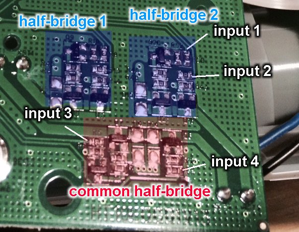
The third photo appears to show a transistor H-bridge controlling the valve with blue and black wires. One side of the H-bridge appears to be shared by both valves.

enter image description here

I suspect the valves are magnetic latching solenoids, and the coils wound around the outside are for the controller to tell when they have operated. A latching solenoid is operated and released by sending a pulse in one direction or the other. You could do this 'manually', by breaking the connections between the control chip and H-bridge inputs, and feeding in digital signals from your own MCU.

The voltage booster may be driven by the control chip and is probably only turned on when needed (ie. a few seconds before operating a valve, and only until the capacitor has charged up), so you might need to provide your own drive for this also. Alternatively you could try charging the capacitor up from an external high voltage source, with a resistor in series to limit current when the valve is operated.

Before doing any hacking you should trace out the circuit and make sure you understand how it works. H-bridges tend to blow up if given the wrong inputs!

\$\endgroup\$
1
  • \$\begingroup\$ You need an oscilloscope to see the valve control signal that will take from 10ms to 50ms. \$\endgroup\$
    – Pedro NF
    Commented Apr 29, 2016 at 8:44
0
\$\begingroup\$

How about using Hall-effect sensors placed near the solenoids? You could then get a voltage pulse out of the sensor every time the solenoid changed position?

\$\endgroup\$

Your Answer

By clicking “Post Your Answer”, you agree to our terms of service and acknowledge you have read our privacy policy.

Not the answer you're looking for? Browse other questions tagged or ask your own question.