1
\$\begingroup\$

I've got a question regarding the location of the resistors used to configure USB. I'm currently designing a board with an STM32 chip, on the left of the diagram and want to have USB broken out, on the right. My question is, does it matter on the order of the resistors, so for instance, should it be the High speed pull up R11 first, and then the 2 termination resistors, or should it be the other way around or does it not matter at all? USB Resistor Locations
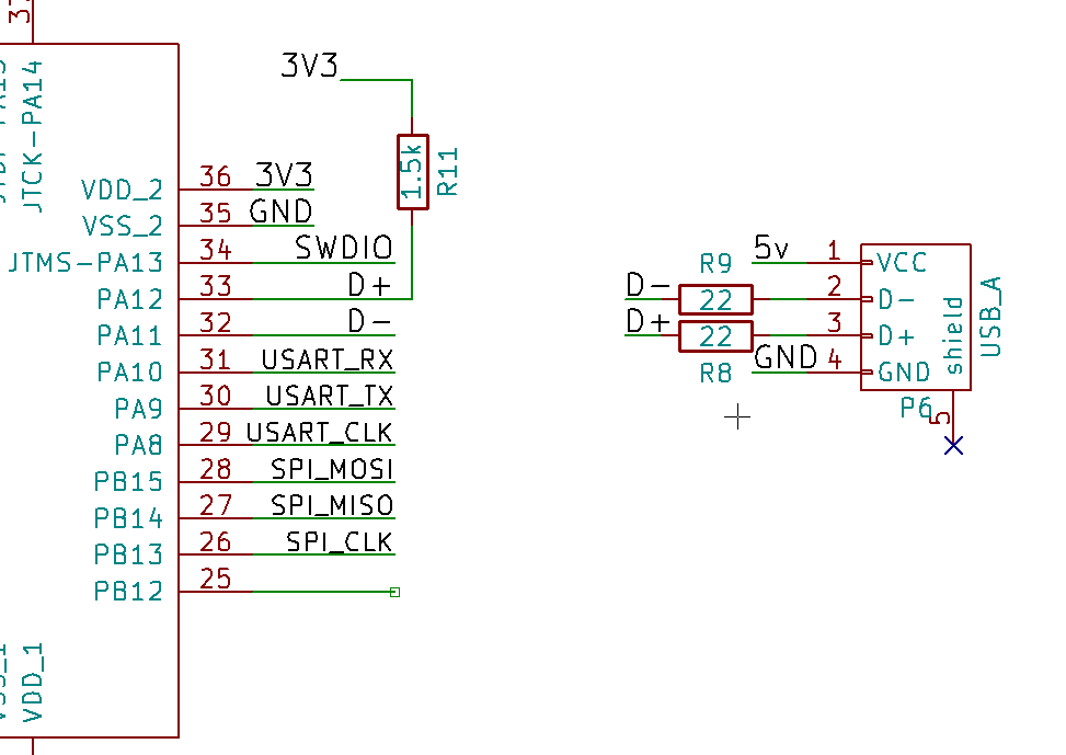
On a side note, is my USB configuration correct? Are the D pins meant to be criss crossed like that?

\$\endgroup\$
5
  • 1
    \$\begingroup\$ Which STM32 are you using? Some of them handle the pull up internally... \$\endgroup\$
    – bitsmack
    Commented Dec 17, 2015 at 16:37
  • 1
    \$\begingroup\$ Most STM32 also have internal impedance matching so the series resistors are not necessary. And the DP/DM signals are not supposed to cross like that. \$\endgroup\$
    – Tony K
    Commented Dec 17, 2015 at 20:18
  • \$\begingroup\$ STM32F103CBT6: Yeah it doesn't apparently need added termination resistors, but it definitely needs the High speed external bias resistor. \$\endgroup\$ Commented Dec 17, 2015 at 23:16
  • \$\begingroup\$ Look at where the black "D+" is in both sections. Those are the same wire. \$\endgroup\$ Commented Dec 19, 2015 at 5:14
  • \$\begingroup\$ Yeah I know, but physically when I route that, assuming the ordering of the schematic matches the ordering of the USB connector pins, the lines are going to be twisted. \$\endgroup\$ Commented Dec 19, 2015 at 5:16

1 Answer 1

2
\$\begingroup\$

I haven't fully found the solution to my problem, but I have been looking at the example schematic for the particular chip I'm designing around. They have the ordering that it goes from chip to termination resistors to the speed select pull up resistor and then to the USB port. So it doesn't fully answer the question of whether ordering is important, but for the time being it at least confirms a correct implementation.

ST link

P.S. the funky transistor setup if anyone's interested is for a software reset on the USB device. R12 and R10 are biasing resistors and it's natively on, then turns off when a bit is written to the USB_RENUMn register. So you can soft reset the device without unplugging the cable.

\$\endgroup\$

Your Answer

By clicking “Post Your Answer”, you agree to our terms of service and acknowledge you have read our privacy policy.

Not the answer you're looking for? Browse other questions tagged or ask your own question.