4
\$\begingroup\$

I am trying to modify a Netgear GS108 8-Port gigabit switch with POE on 4 of the ports. Problem is that when I go to test to find out what pins 4/5 and 7/8 are in order to place the positive and negative terminals too, it shows continuity on every pin of each of the 8!

So in other words, no matter what pin I test for, it always shows continuity so I never know what pin is not being used!

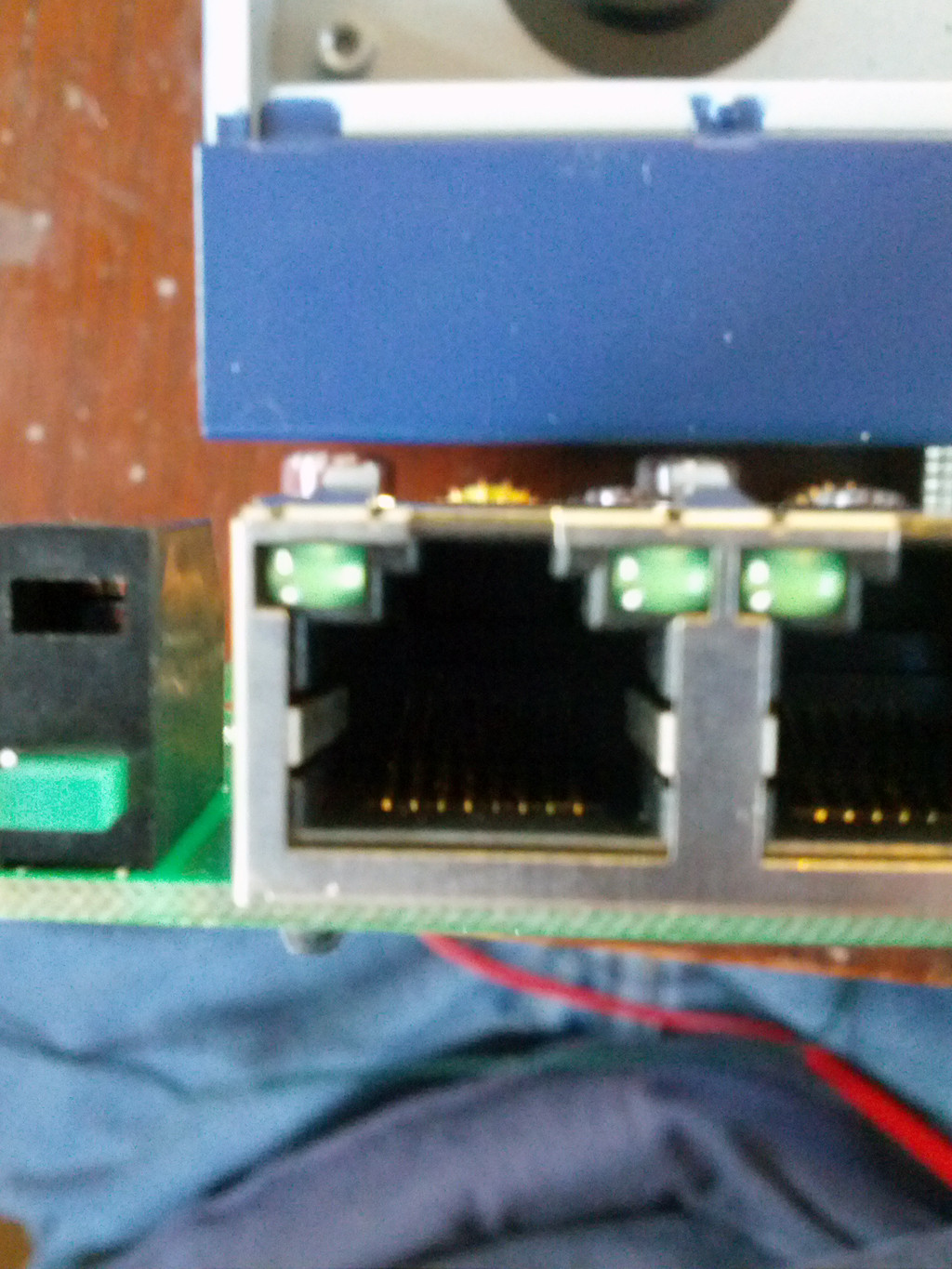
Here is a picture of the board:
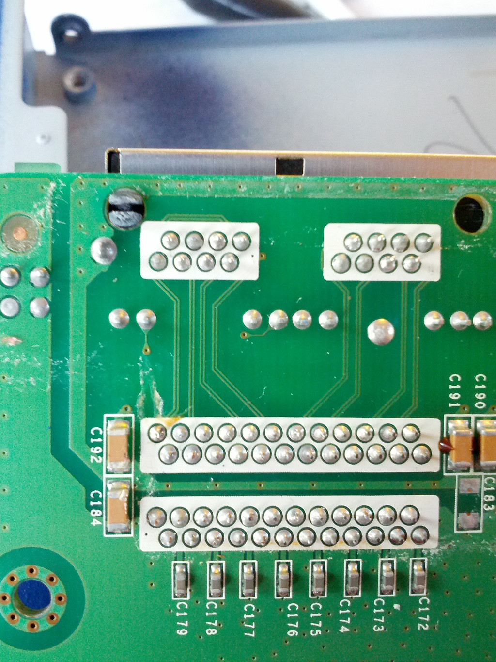
enter image description here enter image description here

Any help would be greatly appreciated since I do not want to fry it :o)

update

If I were to connect pins 4/5 (positive) and 7/8 (negative) to the first 6 ports (ports 1-6) I understand that they would be forced to use 10/100mbps instead of 10/100/1000mbps. That being said, would the other 2 ports (7 & 8) be forced to use 10/100mbps as well or would they operate at the normal 10/100/1000mbps?

\$\endgroup\$
6
  • \$\begingroup\$ What do you mean by "continuity on every pin of echo of the 8" ? \$\endgroup\$
    – 2.718
    Commented Aug 7, 2012 at 1:15
  • 3
    \$\begingroup\$ Also note that GB-Ethernet uses all 4 pairs for data. If you simply connect power as suggested, you will force the port to operate at 100Mbps. \$\endgroup\$
    – 2.718
    Commented Aug 7, 2012 at 1:23
  • \$\begingroup\$ @2.718: Thats what i was afraid of. Thanks for the feedback. \$\endgroup\$
    – StealthRT
    Commented Aug 7, 2012 at 1:26
  • \$\begingroup\$ @2.718: Eaco should be EACH. \$\endgroup\$
    – StealthRT
    Commented Aug 7, 2012 at 13:08
  • \$\begingroup\$ If i were to connect pins 4/5 (positive) and 7/8 (negative) to the first 6 ports (ports 1-6) i understand that they would be forced to use 10/100mbps instead of 10/100/1000mbps. That being said, would the other 2 ports (7 & 8) be forced to use 10/100mbps as well or would they operate at the normal 10/100/1000mbps? \$\endgroup\$
    – StealthRT
    Commented Aug 7, 2012 at 13:08

1 Answer 1

12
\$\begingroup\$

Don't do it! Here's some reasons why you shouldn't:

  • The isolation transformer is not likely to be able to handle the current that PoE will push through it.
  • You can't support the full PoE discovery protocol without modifying the firmware of the Ethernet switch. I am referring to LLDP.
  • Not supporting the PoE discovery protocol could allow you to power a device that isn't able to handle it-- causing it to damage the device.
  • Careful current regulation is required to prevent creating a fire hazzard.

I have to admit that I am making a couple of assumptions about your ability to design this thing properly-- assumptions that might be wrong. I am assuming that you don't know how to design it properly because you don't apparently know how the Ethernet signaling, isolation transformers, and PoE discovery works.

If you knew how PoE and Ethernet actually works then this project might be barely possible-- but hardly cost effective since there are other PoE switches and injectors that are not super expensive. Even as a learning experience this has limited value, since there are better ways to learn PoE.

\$\endgroup\$
1
  • \$\begingroup\$ Thanks for your comment David Kessner! I was looking at instructions here > dd-wrt.com/phpBB2/viewtopic.php?p=101908 and figured i could do the same to power my ip cameras. I have 4 12v 3a power supply's i will need to hook to the pins of the switch. Just didn't know how to go about it since it seems it was all connected to each other. But then again, i was using a multimeter to test the pins and i read that it was not possible to check Ethernet using that method. \$\endgroup\$
    – StealthRT
    Commented Aug 7, 2012 at 13:07

Your Answer

By clicking “Post Your Answer”, you agree to our terms of service and acknowledge you have read our privacy policy.

Not the answer you're looking for? Browse other questions tagged or ask your own question.