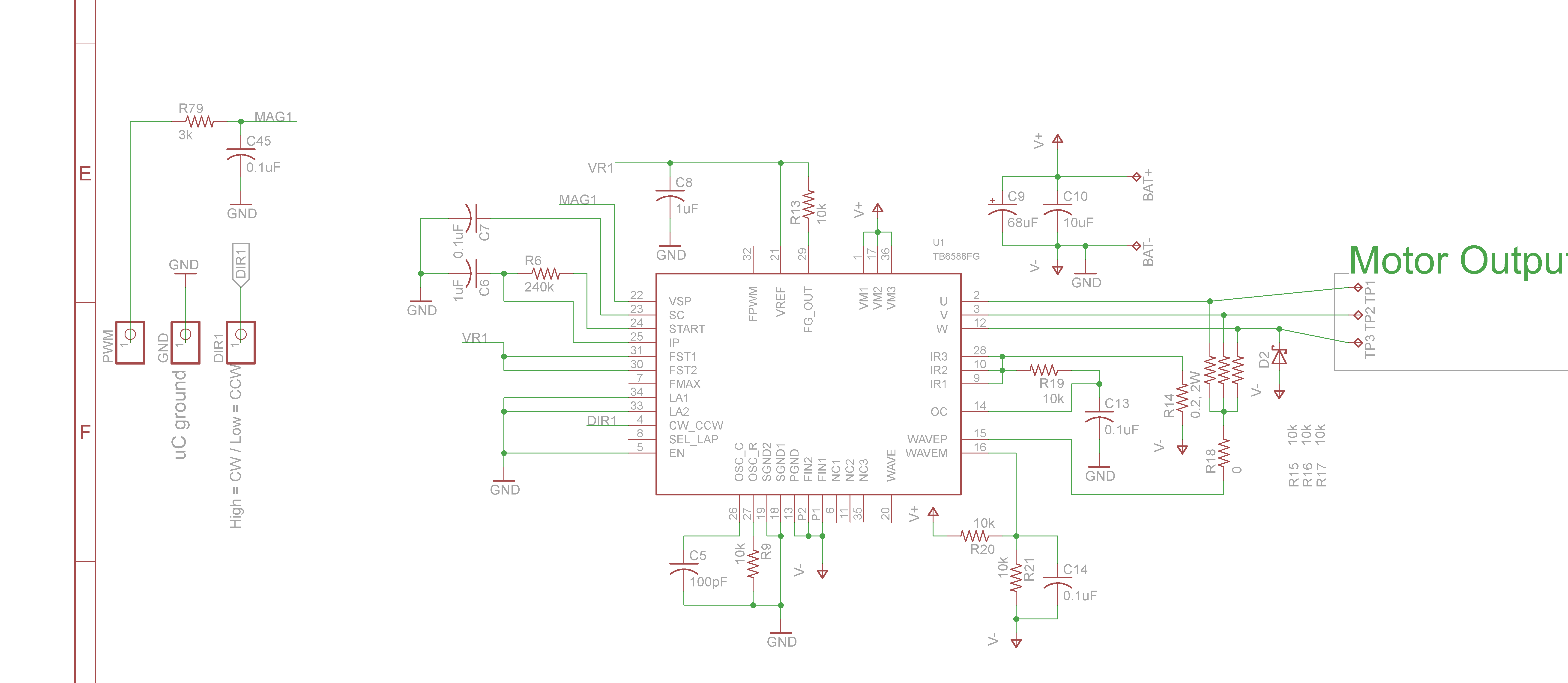
I am trying to make a PCB to control a Sensorless Brushless motor. I just wanted to know if it looks right. The IC I am using is a TB6588FG it has a 2.5A peak output current. I want to use it with this motor. I am going to use a 7.4V battery. The IC needs a analog voltage to change the motor speed. For this I am going to use a first-order RC filter(left side of schematic) to filter the PWM signal. The PWM signal will be supplied by a microcontroller.
\$\begingroup\$
\$\endgroup\$
10
-
1\$\begingroup\$ Is there anything specific that you are concerned about? \$\endgroup\$– JYeltonCommented Aug 13, 2014 at 20:17
-
\$\begingroup\$ I was just wondering if it looks about right? The circuit only needs GND from the MCU which I thought was weird, because how would the IC know the reference voltage. \$\endgroup\$– user33335Commented Aug 13, 2014 at 20:27
-
\$\begingroup\$ I think GND and V- should be joined together. Apart from that your circuit looks good to me. The reference voltage is 5V, but the analog input range is 1.2~4.1V. You can adjust your PWM ratios to match - eg. if your PWM amplitude is 5V then set the minimum ratio to 24% and maximum to 82%. \$\endgroup\$– Bruce AbbottCommented Aug 13, 2014 at 20:55
-
\$\begingroup\$ @BruceAbbott Thank you for responding. Should I tie the reference voltage from the MCU(5V) to V+(Battery)? The small circuit at the top right corner smooths the 7.4V input for the rest of the circuit. Meaning; V+ is equal to 7.4V and V- is the ground. The circuit has no 5V reference. \$\endgroup\$– user33335Commented Aug 13, 2014 at 21:05
-
\$\begingroup\$ You should keep the MCU's +5V separate. You can power it from the 7.4V battery, but only through a regulator which stabilizes the MCU voltage at +5V. The TB6588FG has an internal +5V reference, but it is only good for a few mA. \$\endgroup\$– Bruce AbbottCommented Aug 13, 2014 at 21:30
|
Show 5 more comments