Commonmark migration
Source Link

![enter image description here][1]![enter image description here][2]enter image description hereenter image description here
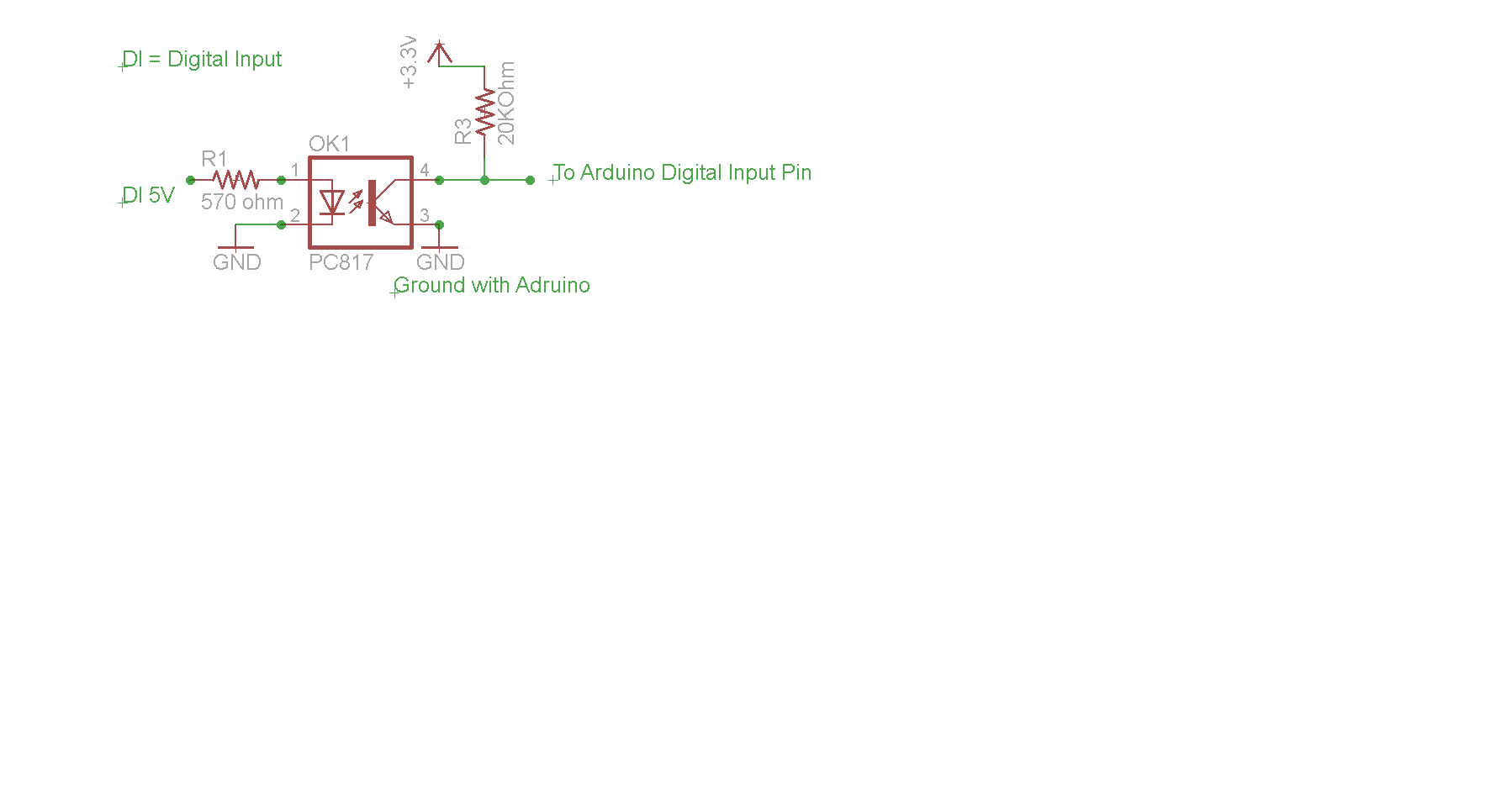
I am using optocoupler PC817 to create optical isolation between my digital signal and arduino due and arduino mega 2560 . And I am using external pull-up resistor connected with 3.3 V (to pull up digital pins of arduino due and arduino mega 2560). And output pin of optocoupler is also attached with the above mentioned 3.3V.

When no digital signal is given to the input pin of optocoupler, its output pin( collector pin, as attached with the externally pulled up pin of arduino) gives 3.3V but when the optocoupler receives digital signal its output pin gives 0V and hence pulling down the input pin of arduino which is taken as input in arduino. It works fine when I give digital signal from external power supply.

But when I give digital signal from function generator(5V at 10Hz), the output of optocoupler does not get to '0' completely rather it gives around 2.5V.

I guess it's the function generator that is causing problem. It is not providing enough current to the LED in optocoupler to glow fully. Could any one help me out how to make optocoupler work when signal is given from function generator?

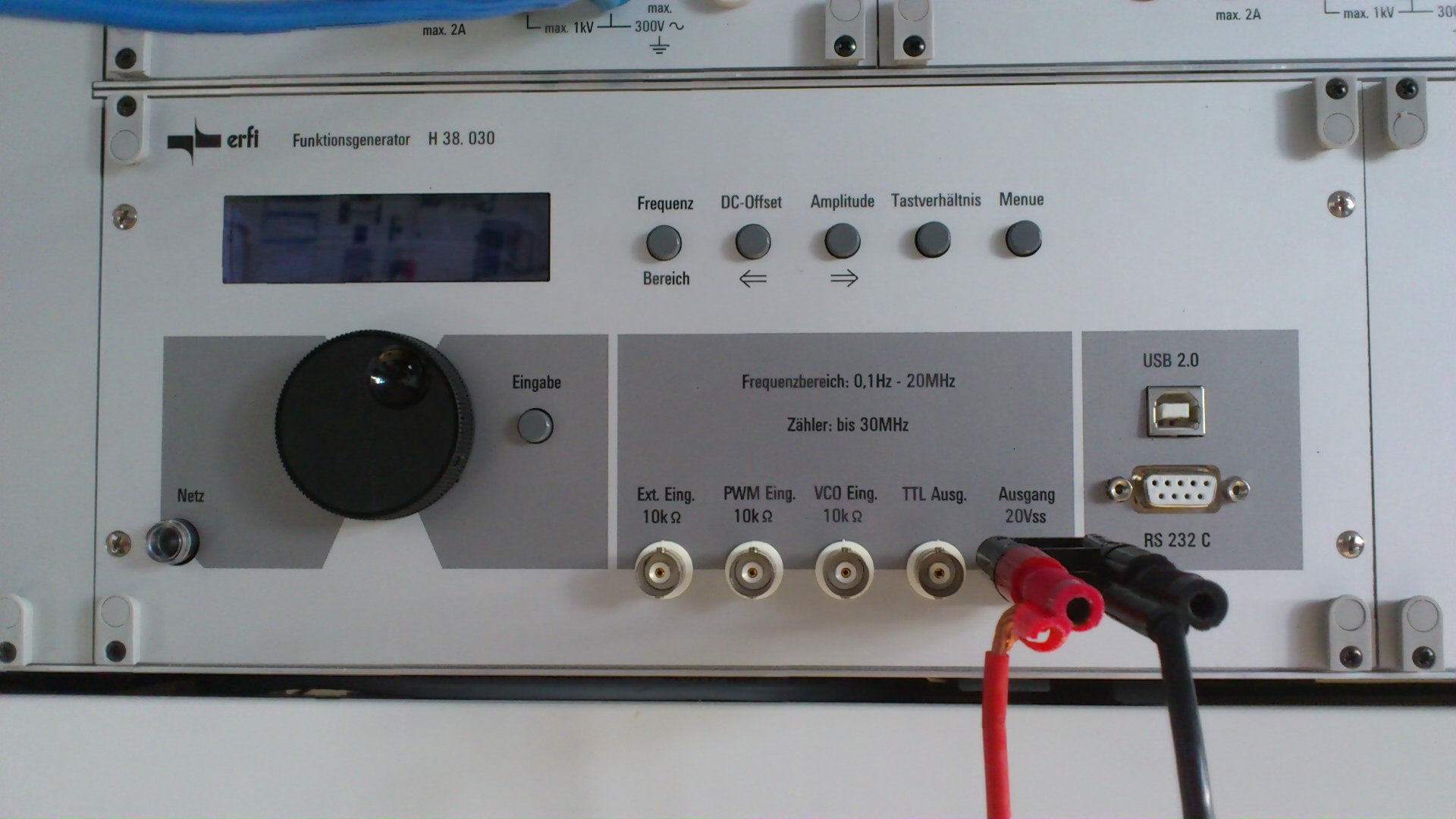
The functiongenerator I am using is shown in the picture below... It is "erfi funktionsgenerator H 38. 030"

Its german function generator and its manual or guide line book is in German... [1]: https://i.sstatic.net/V8A3i.jpg [2]: https://i.sstatic.net/2QTvi.png

![enter image description here][1]![enter image description here][2]
I am using optocoupler PC817 to create optical isolation between my digital signal and arduino due and arduino mega 2560 . And I am using external pull-up resistor connected with 3.3 V (to pull up digital pins of arduino due and arduino mega 2560). And output pin of optocoupler is also attached with the above mentioned 3.3V.

When no digital signal is given to the input pin of optocoupler, its output pin( collector pin, as attached with the externally pulled up pin of arduino) gives 3.3V but when the optocoupler receives digital signal its output pin gives 0V and hence pulling down the input pin of arduino which is taken as input in arduino. It works fine when I give digital signal from external power supply.

But when I give digital signal from function generator(5V at 10Hz), the output of optocoupler does not get to '0' completely rather it gives around 2.5V.

I guess it's the function generator that is causing problem. It is not providing enough current to the LED in optocoupler to glow fully. Could any one help me out how to make optocoupler work when signal is given from function generator?

The functiongenerator I am using is shown in the picture below... It is "erfi funktionsgenerator H 38. 030"

Its german function generator and its manual or guide line book is in German... [1]: https://i.sstatic.net/V8A3i.jpg [2]: https://i.sstatic.net/2QTvi.png

enter image description hereenter image description here
I am using optocoupler PC817 to create optical isolation between my digital signal and arduino due and arduino mega 2560 . And I am using external pull-up resistor connected with 3.3 V (to pull up digital pins of arduino due and arduino mega 2560). And output pin of optocoupler is also attached with the above mentioned 3.3V.

When no digital signal is given to the input pin of optocoupler, its output pin( collector pin, as attached with the externally pulled up pin of arduino) gives 3.3V but when the optocoupler receives digital signal its output pin gives 0V and hence pulling down the input pin of arduino which is taken as input in arduino. It works fine when I give digital signal from external power supply.

But when I give digital signal from function generator(5V at 10Hz), the output of optocoupler does not get to '0' completely rather it gives around 2.5V.

I guess it's the function generator that is causing problem. It is not providing enough current to the LED in optocoupler to glow fully. Could any one help me out how to make optocoupler work when signal is given from function generator?

The functiongenerator I am using is shown in the picture below... It is "erfi funktionsgenerator H 38. 030"

Its german function generator and its manual or guide line book is in German...

added 267 characters in body
Source Link

enter image description here![enter image description here][1]![enter image description here][2]
I am using optocoupler PC817 to create optical isolation between my digital signal and arduino due and arduino mega 2560 . And I am using external pull-up resistor connected with 3.3 V (to pull up digital pins of arduino due and arduino mega 2560). And output pin of optocoupler is also attached with the above mentioned 3.3V.

When no digital signal is given to the input pin of optocoupler, its output pin( collector pin, as attached with the externally pulled up pin of arduino) gives 3.3V but when the optocoupler receives digital signal its output pin gives 0V and hence pulling down the input pin of arduino which is taken as input in arduino. It works fine when I give digital signal from external power supply.

But when I give digital signal from function generator(5V at 10Hz), the output of optocoupler does not get to '0' completely rather it gives around 2.5V.

I guess it's the function generator that is causing problem. It is not providing enough current to the LED in optocoupler to glow fully. Could any one help me out how to make optocoupler work when signal is given from function generator?

The functiongenerator I am using is shown in the picture below... It is "erfi funktionsgenerator H 38. 030"

Its german function generator and its manual or guide line book is in German... [1]: https://i.sstatic.net/V8A3i.jpg [2]: https://i.sstatic.net/2QTvi.png

enter image description here
I am using optocoupler PC817 to create optical isolation between my digital signal and arduino due and arduino mega 2560 . And I am using external pull-up resistor connected with 3.3 V (to pull up digital pins of arduino due and arduino mega 2560). And output pin of optocoupler is also attached with the above mentioned 3.3V.

When no digital signal is given to the input pin of optocoupler, its output pin( collector pin, as attached with the externally pulled up pin of arduino) gives 3.3V but when the optocoupler receives digital signal its output pin gives 0V and hence pulling down the input pin of arduino which is taken as input in arduino. It works fine when I give digital signal from external power supply.

But when I give digital signal from function generator(5V at 10Hz), the output of optocoupler does not get to '0' completely rather it gives around 2.5V.

I guess it's the function generator that is causing problem. It is not providing enough current to the LED in optocoupler to glow fully. Could any one help me out how to make optocoupler work when signal is given from function generator?

![enter image description here][1]![enter image description here][2]
I am using optocoupler PC817 to create optical isolation between my digital signal and arduino due and arduino mega 2560 . And I am using external pull-up resistor connected with 3.3 V (to pull up digital pins of arduino due and arduino mega 2560). And output pin of optocoupler is also attached with the above mentioned 3.3V.

When no digital signal is given to the input pin of optocoupler, its output pin( collector pin, as attached with the externally pulled up pin of arduino) gives 3.3V but when the optocoupler receives digital signal its output pin gives 0V and hence pulling down the input pin of arduino which is taken as input in arduino. It works fine when I give digital signal from external power supply.

But when I give digital signal from function generator(5V at 10Hz), the output of optocoupler does not get to '0' completely rather it gives around 2.5V.

I guess it's the function generator that is causing problem. It is not providing enough current to the LED in optocoupler to glow fully. Could any one help me out how to make optocoupler work when signal is given from function generator?

The functiongenerator I am using is shown in the picture below... It is "erfi funktionsgenerator H 38. 030"

Its german function generator and its manual or guide line book is in German... [1]: https://i.sstatic.net/V8A3i.jpg [2]: https://i.sstatic.net/2QTvi.png

added 12 characters in body
Source Link

enter image description here
I am using optocoupler PC817 to create optical isolation between my digital signal and arduino due and arduino mega 2560 . And I am using external pull-up resistor connected with 3.3 V (to pull up digital pins of arduino due and arduino mega 2560). And output pin of optocoupler is also attached with the above mentioned 3.3V.

When no digital signal is given to the input pin of optocoupler, its output pin( collector pin, as attached with the externally pulled up pin of arduino) gives 3.3V but when the optocoupler receives digital signal its output pin gives 0V and hence pulling down the input pin of arduino which is taken as input in arduino. It works fine when I give digital signal from external power supply.

But when I give digital signal from function generator(5V at 10Hz), the output of optocoupler does not get to '0' completely rather it gives around 2.5V.

I guess it's the function generator that is causing problem. It is not providing enough current to the LED in optocoupler to glow fully. Could any one help me out how to make optocoupler work when signal is given from function generator?

enter image description here
I am using optocoupler PC817 to create optical isolation between my digital signal and arduino due and arduino mega 2560 . And I am using external pull-up resistor connected with 3.3 V (to pull up digital pins of arduino due and arduino mega 2560). And output pin of optocoupler is also attached with the above mentioned 3.3V.

When no digital signal is given to the input pin of optocoupler, its output pin( collector pin, as attached with the externally pulled up pin of arduino) gives 3.3V but when the optocoupler receives digital signal its output pin gives 0V and hence pulling down the input pin of arduino which is taken as input in arduino. It works fine when I give digital signal from external power supply.

But when I give digital signal from function generator, the output of optocoupler does not get to '0' completely rather it gives around 2.5V.

I guess it's the function generator that is causing problem. It is not providing enough current to the LED in optocoupler to glow fully. Could any one help me out how to make optocoupler work when signal is given from function generator?

enter image description here
I am using optocoupler PC817 to create optical isolation between my digital signal and arduino due and arduino mega 2560 . And I am using external pull-up resistor connected with 3.3 V (to pull up digital pins of arduino due and arduino mega 2560). And output pin of optocoupler is also attached with the above mentioned 3.3V.

When no digital signal is given to the input pin of optocoupler, its output pin( collector pin, as attached with the externally pulled up pin of arduino) gives 3.3V but when the optocoupler receives digital signal its output pin gives 0V and hence pulling down the input pin of arduino which is taken as input in arduino. It works fine when I give digital signal from external power supply.

But when I give digital signal from function generator(5V at 10Hz), the output of optocoupler does not get to '0' completely rather it gives around 2.5V.

I guess it's the function generator that is causing problem. It is not providing enough current to the LED in optocoupler to glow fully. Could any one help me out how to make optocoupler work when signal is given from function generator?

spelling and such
Source Link
Nick Alexeev
  • 38.6k
  • 17
  • 101
  • 240
Loading
added 81 characters in body
Source Link
Loading
Source Link
Loading