Commonmark migration
Source Link

A quick search led me to this:

Sense (tachometer) provides two pulses per revolution of fan. Output is open-collector and main board must have pull-up resistor to 12V.


Signal Control (PWM) is input for PWM pulses. Base frequency is 25kHz and it is acceptable from 21kHz to 28kHz. Input has TTL level and includes pull-up resistor to 5V or to 3.3V in new constructions. Signal is not inverted and 100% PWM means maximal revolutions of fan. Motherboard has open-collector type output. This construction guarantee, that with disconnected PWM signal will runs fan with maximum revolutions.

So in theory, you could use a 555 timer that produces a PWM signal based on a potentiometer input. Or simply anything capable of doing 25kHz PWM.

An example of the Triple-Five-Timer being used in such a way below. (Note that it's not from my head, found it here. Hope I didn't mess something up.) Also note, that I did not bother calculating proper values for that 25kHz operation.
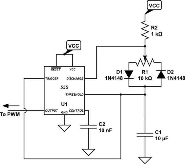
schematic

simulate this circuit – Schematic created using CircuitLab

Basically you adjust the discharge/charge rate of the C capacitor by sweeping the R1 pot. All there is to it. The rest is just use of the 555 magic.


That said, I'd consider replacing the transistor. That is IMO the most relevant solution.

A quick search led me to this:

Sense (tachometer) provides two pulses per revolution of fan. Output is open-collector and main board must have pull-up resistor to 12V.

Signal Control (PWM) is input for PWM pulses. Base frequency is 25kHz and it is acceptable from 21kHz to 28kHz. Input has TTL level and includes pull-up resistor to 5V or to 3.3V in new constructions. Signal is not inverted and 100% PWM means maximal revolutions of fan. Motherboard has open-collector type output. This construction guarantee, that with disconnected PWM signal will runs fan with maximum revolutions.

So in theory, you could use a 555 timer that produces a PWM signal based on a potentiometer input. Or simply anything capable of doing 25kHz PWM.

An example of the Triple-Five-Timer being used in such a way below. (Note that it's not from my head, found it here. Hope I didn't mess something up.) Also note, that I did not bother calculating proper values for that 25kHz operation.

schematic

simulate this circuit – Schematic created using CircuitLab

Basically you adjust the discharge/charge rate of the C capacitor by sweeping the R1 pot. All there is to it. The rest is just use of the 555 magic.


That said, I'd consider replacing the transistor. That is IMO the most relevant solution.

added 1222 characters in body
Source Link
Dzarda
  • 3.1k
  • 1
  • 18
  • 23

A quick search led me to this. I don't know if it answers at least a bit of what you're asking.:

Sense (tachometer) provides two pulses per revolution of fan. Output is open-collector and main board must have pull-up resistor to 12V.

Signal Control (PWM) is input for PWM pulses. Base frequency is 25kHz and it is acceptable from 21kHz to 28kHz. Input has TTL level and includes pull-up resistor to 5V or to 3.3V in new constructions. Signal is not inverted and 100% PWM means maximal revolutions of fan. Motherboard has open-collector type output. This construction guarantee, that with disconnected PWM signal will runs fan with maximum revolutions.

So in theory, you could use a 555 timer that produces a PWM signal based on a potentiometer input. Or simply anything capable of doing 25kHz PWM.

An example of the Triple-Five-Timer being used in such a way below. (Note that it's not from my head, found it here. Hope I didn't mess something up.) Also note, that I did not bother calculating proper values for that 25kHz operation.

schematic

simulate this circuit – Schematic created using CircuitLab

Basically you adjust the discharge/charge rate of the C capacitor by sweeping the R1 pot. All there is to it. The rest is just use of the 555 magic.


That said, I'd consider replacing the transistor. That is IMO the most relevant solution.

A quick search led me to this. I don't know if it answers at least a bit of what you're asking.

So in theory, you could use a 555 timer that produces a PWM signal based on a potentiometer input.


That said, I'd consider replacing the transistor. That is IMO the most relevant solution.

A quick search led me to this:

Sense (tachometer) provides two pulses per revolution of fan. Output is open-collector and main board must have pull-up resistor to 12V.

Signal Control (PWM) is input for PWM pulses. Base frequency is 25kHz and it is acceptable from 21kHz to 28kHz. Input has TTL level and includes pull-up resistor to 5V or to 3.3V in new constructions. Signal is not inverted and 100% PWM means maximal revolutions of fan. Motherboard has open-collector type output. This construction guarantee, that with disconnected PWM signal will runs fan with maximum revolutions.

So in theory, you could use a 555 timer that produces a PWM signal based on a potentiometer input. Or simply anything capable of doing 25kHz PWM.

An example of the Triple-Five-Timer being used in such a way below. (Note that it's not from my head, found it here. Hope I didn't mess something up.) Also note, that I did not bother calculating proper values for that 25kHz operation.

schematic

simulate this circuit – Schematic created using CircuitLab

Basically you adjust the discharge/charge rate of the C capacitor by sweeping the R1 pot. All there is to it. The rest is just use of the 555 magic.


That said, I'd consider replacing the transistor. That is IMO the most relevant solution.

Source Link
Dzarda
  • 3.1k
  • 1
  • 18
  • 23

A quick search led me to this. I don't know if it answers at least a bit of what you're asking.

So in theory, you could use a 555 timer that produces a PWM signal based on a potentiometer input.


That said, I'd consider replacing the transistor. That is IMO the most relevant solution.