added 122 characters in body
Source Link
Adi
  • 300
  • 4
  • 15

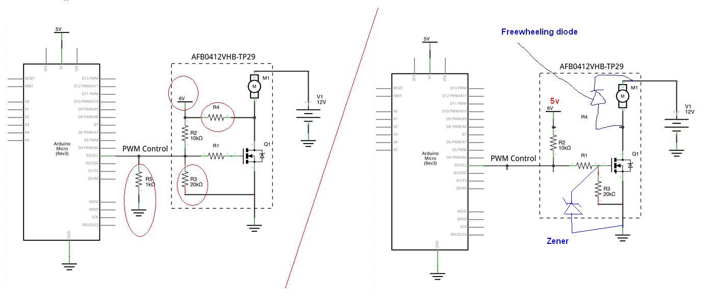
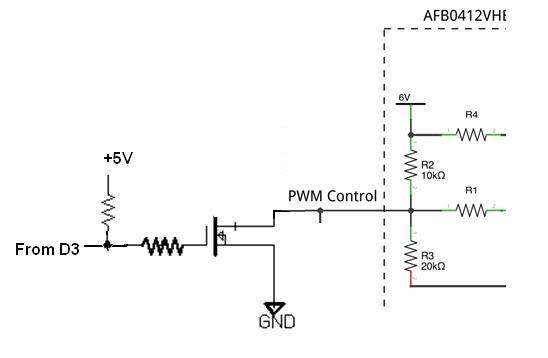
Have a look at the below corrected diagram . 1). You should add a freewheeling diode at the motor terminal to catter inductive kicks. 2)If you need further protection you can isolate the microcontroller section from the MOSFET via an optocoupler, and there power supplies respectively. 3) Add a zener at the base of the Mosfet to protect the gate at what ever, voltage you are operating the FET.You may also try adding an inverter stage to switch off the FET on power offenter image description here. @Ivan ,I missed your datasheet anyways, Try using an inverter in between D3 and rest of the ckt of yours. Sometyhing like this; enter image description here
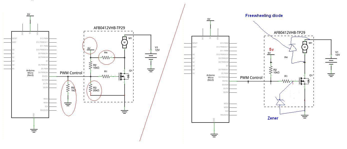
Have a look at the below corrected diagram . 1). You should add a freewheeling diode at the motor terminal to catter inductive kicks. 2)If you need further protection you can isolate the microcontroller section from the MOSFET via an optocoupler, and there power supplies respectively. 3) Add a zener at the base of the Mosfet to protect the gate at what ever, voltage you are operating the FET.You may also try adding an inverter stage to switch off the FET on power offenter image description here

Have a look at the below corrected diagram . 1). You should add a freewheeling diode at the motor terminal to catter inductive kicks. 2)If you need further protection you can isolate the microcontroller section from the MOSFET via an optocoupler, and there power supplies respectively. 3) Add a zener at the base of the Mosfet to protect the gate at what ever, voltage you are operating the FET.You may also try adding an inverter stage to switch off the FET on power off. @Ivan ,I missed your datasheet anyways, Try using an inverter in between D3 and rest of the ckt of yours. Sometyhing like this; enter image description here

added 76 characters in body
Source Link
Adi
  • 300
  • 4
  • 15

Have a look at the below corrected diagram . 1). You should add a freewheeling diode at the motor terminal to catter inductive kicks. 2)If you need further protection you can isolate the microcontroller section from the MOSFET via an optocoupler, and there power supplies respectively. 3) Add a zener at the base of the Mosfet to protect the gate at what ever, voltage you are operating the FET.You may also try adding an inverter stage to switch off the FET on power offenter image description here

Have a look at the below corrected diagram . 1). You should add a freewheeling diode at the motor terminal to catter inductive kicks. 2)If you need further protection you can isolate the microcontroller section from the MOSFET via an optocoupler, and there power supplies respectively. 3) Add a zener at the base of the Mosfet to protect the gate at what ever, voltage you are operating the FET.enter image description here

Have a look at the below corrected diagram . 1). You should add a freewheeling diode at the motor terminal to catter inductive kicks. 2)If you need further protection you can isolate the microcontroller section from the MOSFET via an optocoupler, and there power supplies respectively. 3) Add a zener at the base of the Mosfet to protect the gate at what ever, voltage you are operating the FET.You may also try adding an inverter stage to switch off the FET on power offenter image description here

added 5 characters in body
Source Link
Adi
  • 300
  • 4
  • 15

Have a look at the below corrected diagram . 1). You should add a freewheeling diode at the motor terminal to catter inductive kicks. 2)If you need further protection you can isolate the microcontroller section from the MOSFET via an optocoupler, and there power supplies respectively. 3) Add a zener at the base of the Mosfet to protect the gate at what ever, voltage you are operating the FET.enter image description hereenter image description here

Have a look at the below corrected diagram . 1). You should add a freewheeling diode at the motor terminal to catter inductive kicks. 2)If you need further protection you can isolate the microcontroller section from the MOSFET via an optocoupler, and there power supplies respectively. 3) Add a zener at the base of the Mosfet to protect the gate at what ever, voltage you are operating the FET.enter image description here

Have a look at the below corrected diagram . 1). You should add a freewheeling diode at the motor terminal to catter inductive kicks. 2)If you need further protection you can isolate the microcontroller section from the MOSFET via an optocoupler, and there power supplies respectively. 3) Add a zener at the base of the Mosfet to protect the gate at what ever, voltage you are operating the FET.enter image description here

Source Link
Adi
  • 300
  • 4
  • 15
Loading