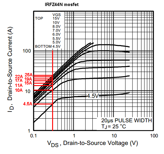
If you look at the on resistance characteristic of an IRFZ44N (for instance) it is like this: -

I've drawn a vertical red line that corresponds to a drain-source voltage of 0.3V and if you look at the horizontal lines I've drawn you should see that for this volt-drop there can be several different values of current thru the drain.
These several different values (ranging from 4.5 amps to 25 amps) correspond to the drive voltage on the gate. So with a 4.5 volts drive voltage on the gate, the on-resistance will be 0.3 volts / 4.5 amps = 67 milli ohms. When the gate voltage is 15 volts, the on-resistance will be 0.3 volts / 25 amps = 12 milli ohms.
Clearly, you can expect that the on resistance will be lower when the gate voltage is higher. When the on-resistance is lower, for a given current, the power loss (\$I^2R\$) will be smaller.
By the way, these above are "conduction losses" and not "switching losses" although switching losses can be improved with higher gate drives (and faster gate drives). Switching losses are when the MOSFET turns from a high-open impedance to a low on-impedance - the in-between period is determined by the speed of the MOSFET's driver - slower speed means the MOSFET spends a longer time at some value of resistance that is neither fully-on or fully-off.
