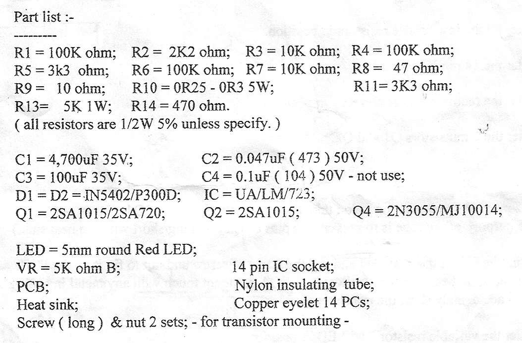
I'm trying to troubleshoot a delinquent power supply I have. Most recently one of the transistors (Q1) actually exploded on it. This has led me into investigating the schematic, but try as I might, I can't make heads nor tails of what's going on. I'm an electrical engineer (but optics) and will admit being a complete noob with electronics, but I'm trying to change that.
I've attached the circuit diagram. For starters, rather than "HOW DOES THIS THING WORK," my more specific question is how the UA/LM723 operates in the circuit; that is, what is its job, and how does it do it? I have seen another LM723 in almost the exact same setup elsewhere, but the site was in Russian. I have also spent about half a day playing around with the various configurations on the datasheet to try and get a feel for how it works. However, I don't understand:
a) why the zener is shorted to ground, and the effect of this (I have seen it either greatly limit the range of Vo, or make the whole thing unstable) b) what the role of the LM723 is in this circuit. I understand that it is responsible for varying the voltage (and regulating it), how is it accomplishing this? c) BONUS, if not too strenuous, I know that Q3/4 is likely the main pass transistor and thus responsible for full current handling, but what are Q1 and Q2 doing?
I'm quite lost after spending some time monkeying with this, so any direction is greatly appreciated.


UPDATE: I checked the 3055, and it has 550 ohms from emitter to base (i.e., black lead on emitter); and about the same from collector to base (black lead on collector). Everything else HI. I think that my pinout is correct (used http://www.rmcybernetics.com/images/users/diy_coildriverSd2gH5.jpg).
