New schematic
Source Link
venny
  • 3.1k
  • 14
  • 16

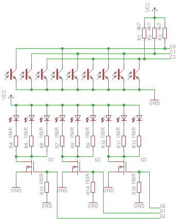
Take a look at this simple matrix circuit. It requires only sqrt(n)*2 GPIOs. Scanning through 'rows' is done by turning the IR LEDs on and off. Only one 'row' is lit at a time, which also saves power.

It shows 9 sensors in 3x3 matrix connected to 6 GPIOs.
cir

External transistors are needed because with larger number of LEDs, the current draw gets significant. Either N-MOSFET or NPN will do. G[0..2] is input for switching LEDs, C[0..2] is output from phototransistors. Light=logic low, no light=logic high.

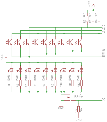
Edit: as @gbulmer pointed out, it is important to cancel out any ambient light. To do this, circuit has to be slightly modified - emitters of phototransistors E[0..2] are switched between low (photocurrent, either from leds or ambient, can flow) and tri-state (no photocurrent). LEDs may be switched all at once or in groups as in previuos circuit. Outputs C[0..2] are read by ADC, first with LEDs off and then with LEDs on.
cir2

Take a look at this simple matrix circuit. It requires only sqrt(n)*2 GPIOs. Scanning through 'rows' is done by turning the IR LEDs on and off. Only one 'row' is lit at a time, which also saves power.

It shows 9 sensors in 3x3 matrix connected to 6 GPIOs.

cir

External transistors are needed because with larger number of LEDs, the current draw gets significant. Either N-MOSFET or NPN will do. G[0..2] is input for switching LEDs, C[0..2] is output from phototransistors. Light=logic low, no light=logic high.

Edit: as @gbulmer pointed out, it is important to cancel out any ambient light. To do this, circuit has to be slightly modified - emitters of phototransistors E[0..2] are switched between low (photocurrent, either from leds or ambient, can flow) and tri-state (no photocurrent). LEDs may be switched all at once or in groups as in previuos circuit. Outputs C[0..2] are read by ADC, first with LEDs off and then with LEDs on.

cir2

Source Link
venny
  • 3.1k
  • 14
  • 16

Take a look at this simple matrix circuit. It requires only sqrt(n)*2 GPIOs. Scanning through 'rows' is done by turning the IR LEDs on and off. Only one 'row' is lit at a time, which also saves power.

It shows 9 sensors in 3x3 matrix connected to 6 GPIOs.

cir

External transistors are needed because with larger number of LEDs, the current draw gets significant. Either N-MOSFET or NPN will do. G[0..2] is input for switching LEDs, C[0..2] is output from phototransistors. Light=logic low, no light=logic high.