Automotive power is one of the more notoriously annoying sources of noise there is.
You need to imagine a lot of high voltage, high frequency spikes happening on the power, this couples and radiates into your set-up, where up-flanks can be so fast and strong they couple into your VCC through your converter, as the converter has only a certain amount of noise rejection. The down flanks can push so hard they will show up in the ground you see at your device. And even more complex annoyances to do with coupling and propagation of noise sources.
The only way to get rid of those and know exactly why you do what you do is to look for a tutorial about automotive power noise filtering and seeing which of the explained steps you have not yet taken yourself.
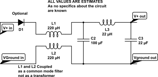
But a good start would be to include a common-mode input filter coil on the entirety of your power that's rated for automotive filtering. Many inductor factories make them, I like Würth Electronic, but that's also because they have a very permissive sampling regimen. After that, obviously you put a nice strong capacitor: Capacitance able to provide the current needed to your circuit for about 1ms of full drop-out and low ESR to get out as much noise as possible. You may also put an input diode onto the system to protect even better against full "disappearance" of power for about 1ms, so that you don't power other stuff from "your personal capacitor".
After that capacitor you can add another inductance on the positive rail, followed by the input capacitance required for your regulator.
Edit1: Schematic coming up to clarify... Edit2: Sorry, forgot to save the edit once I was done calling :-S

simulate this circuit – Schematic created using CircuitLab
