added 40 characters in body
Source Link
Dan Laks
  • 8.6k
  • 4
  • 29
  • 44

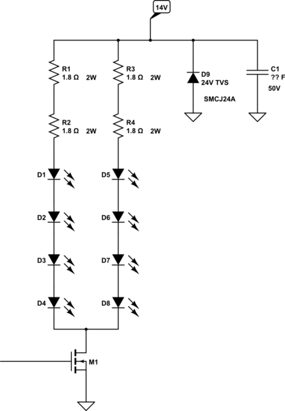
Try this circuit for your LEDs. ThereThere is no reason to use a regulator for the diode string. It is just wasted heat and power. Also paralleling LEDs without a series resistor on each LED will cause them to not share the current equally. The one with the lowest forward voltage (based on manufacturing variability) will take the most current. This circuit will give you the same light as your current circuit for 1.4 amps and generate way less heat. I used 2 resistors in series to share the heat and I needed 3.6 Ohms, which is not a standard value. 

You can use more strings for more light or if you use a PWM signal with a maximum duty cycle of 50% to drive Q1 and change the resistors to 0.7 Ohms, you will get almost twice the light for the same average power. MakeMake sure you switch at a reasonable frequency like 200Hz-1KHz and make sure your heat sink is adequate. It also may be a good idea to add a good low ESR cap between the 14V and ground to prevent any switching noise. The value of the cap will depend on your frequency but make sure it is at least 50V. On

On a side note you do not need the NPN transistor to drive the MOSFET if you use one with a logic level gate. Make sure your MOSFET has a breakdown voltage of 55v or greater to prevent damage from the load dump that occurs when your starter motor turns off. This can cause very large voltages on the 14V buss. I always put a unidirectional TVS diode between the 14V and Ground (Cathode to 14V). Anything in the 24v-30v range should work. It will also prevent damage from static electricity. Good Luck!
schematic

simulate this circuit – Schematic created using CircuitLab

Try this circuit for your LEDs. There is no reason to use a regulator for the diode string. It is just wasted heat and power. Also paralleling LEDs without a series resistor on each LED will cause them to not share the current equally. The one with the lowest forward voltage will take the most current. This circuit will give you the same light as your current circuit for 1.4 amps and generate way less heat. I used 2 resistors in series to share the heat and I needed 3.6 Ohms, which is not a standard value. You can use more strings for more light or if you use a PWM signal with a maximum duty cycle of 50% to drive Q1 and change the resistors to 0.7 Ohms, you will get almost twice the light for the same average power. Make sure you switch at a reasonable frequency like 200Hz-1KHz and make sure your heat sink is adequate. It also may be a good idea to add a good low ESR cap between the 14V and ground to prevent any switching noise. The value of the cap will depend on your frequency but make sure it is at least 50V. On a side note you do not need the NPN transistor to drive the MOSFET if you use one with a logic level gate. Make sure your MOSFET has a breakdown voltage of 55v or greater to prevent damage from the load dump that occurs when your starter motor turns off. This can cause very large voltages on the 14V buss. I always put a unidirectional TVS diode between the 14V and Ground (Cathode to 14V). Anything in the 24v-30v range should work. It will also prevent damage from static electricity. Good Luck!

schematic

simulate this circuit – Schematic created using CircuitLab

Try this circuit for your LEDs. There is no reason to use a regulator for the diode string. It is just wasted heat and power. Also paralleling LEDs without a series resistor on each LED will cause them to not share the current equally. The one with the lowest forward voltage (based on manufacturing variability) will take the most current. This circuit will give you the same light as your current circuit for 1.4 amps and generate way less heat. I used 2 resistors in series to share the heat and I needed 3.6 Ohms, which is not a standard value. 

You can use more strings for more light or if you use a PWM signal with a maximum duty cycle of 50% to drive Q1 and change the resistors to 0.7 Ohms, you will get almost twice the light for the same average power. Make sure you switch at a reasonable frequency like 200Hz-1KHz and make sure your heat sink is adequate. It also may be a good idea to add a good low ESR cap between the 14V and ground to prevent any switching noise. The value of the cap will depend on your frequency but make sure it is at least 50V.

On a side note you do not need the NPN transistor to drive the MOSFET if you use one with a logic level gate. Make sure your MOSFET has a breakdown voltage of 55v or greater to prevent damage from the load dump that occurs when your starter motor turns off. This can cause very large voltages on the 14V buss. I always put a unidirectional TVS diode between the 14V and Ground (Cathode to 14V). Anything in the 24v-30v range should work. It will also prevent damage from static electricity. Good Luck!

schematic

simulate this circuit – Schematic created using CircuitLab

Source Link
GlenB
  • 11
  • 1

Try this circuit for your LEDs. There is no reason to use a regulator for the diode string. It is just wasted heat and power. Also paralleling LEDs without a series resistor on each LED will cause them to not share the current equally. The one with the lowest forward voltage will take the most current. This circuit will give you the same light as your current circuit for 1.4 amps and generate way less heat. I used 2 resistors in series to share the heat and I needed 3.6 Ohms, which is not a standard value. You can use more strings for more light or if you use a PWM signal with a maximum duty cycle of 50% to drive Q1 and change the resistors to 0.7 Ohms, you will get almost twice the light for the same average power. Make sure you switch at a reasonable frequency like 200Hz-1KHz and make sure your heat sink is adequate. It also may be a good idea to add a good low ESR cap between the 14V and ground to prevent any switching noise. The value of the cap will depend on your frequency but make sure it is at least 50V. On a side note you do not need the NPN transistor to drive the MOSFET if you use one with a logic level gate. Make sure your MOSFET has a breakdown voltage of 55v or greater to prevent damage from the load dump that occurs when your starter motor turns off. This can cause very large voltages on the 14V buss. I always put a unidirectional TVS diode between the 14V and Ground (Cathode to 14V). Anything in the 24v-30v range should work. It will also prevent damage from static electricity. Good Luck!

schematic

simulate this circuit – Schematic created using CircuitLab