Removed part of title in excess
Link
clabacchio
  • 13.6k
  • 4
  • 45
  • 80

Questions on Operational Amplifiers & Bridge Rectifiers

edited tags
Link
clabacchio
  • 13.6k
  • 4
  • 45
  • 80
Removed second question
Source Link
clabacchio
  • 13.6k
  • 4
  • 45
  • 80

What I've learned so far from Navy school is that operational amplifiers are used as a substitute for transistor amplifiers and they contain three main circuits: the differential amplifier, common collector amplifier and the push-pull amplifier. They are represented by a triangle pointing to the right. My question is, why is the voltage gain \$-\frac{R_f}{R_i}\$
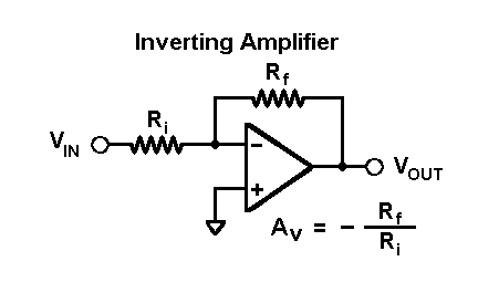
enter image description here

As far as I know, \$R_f\$ provides negative feedback to \$v_{in}\$, but why are we not treating \$R_{in}\$ and \$R_f\$ as part of a voltage divider like a non-inverting amplifier? I can see how they would reason that the incoming current is \$-\frac{v_{in}}{R_{in}}\$ without the voltage divider

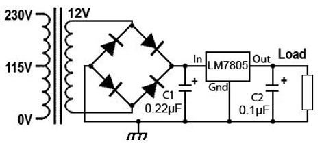
My other question has to do with a bridge rectifier. I had an operational amp test today and did not understand how to answer questions related to what certain components did in a circuit. If I added a load resistor to a bridge rectifier would that decrease the AC ripple and increase the output voltage? Is that load resistor used to prevent the capacitor C2 from conducting? enter image description here

What I've learned so far from Navy school is that operational amplifiers are used as a substitute for transistor amplifiers and they contain three main circuits: the differential amplifier, common collector amplifier and the push-pull amplifier. They are represented by a triangle pointing to the right. My question is, why is the voltage gain \$-\frac{R_f}{R_i}\$

enter image description here

As far as I know, \$R_f\$ provides negative feedback to \$v_{in}\$, but why are we not treating \$R_{in}\$ and \$R_f\$ as part of a voltage divider like a non-inverting amplifier? I can see how they would reason that the incoming current is \$-\frac{v_{in}}{R_{in}}\$ without the voltage divider

added 69 characters in body
Source Link
Loading
Source Link
Loading