It will be necessary to understand the current sinking capability of the open-collector driver on the output pins. You will also need to know the off state voltage that the open-collector driver can withstand without damage. It will be necessary to not exceed either one of these parameters.
Next step is to comprehend the relay coil requirements for the two relays. How much voltage needs to be applied across the relay coil to be able to pull-in the relay and how much current flows through the relay coil when it is energized. If the two relays are the same then they can be wired in parallel. On the other hand if the two relays require different voltages you will require buffering and a separate driver stage for each relay.
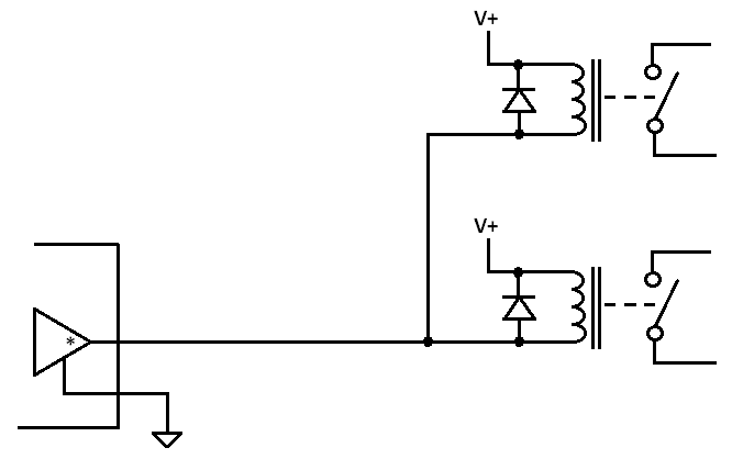
It the sum of the current for each of the two relay coils is less than the current sink capability of the open-collector output AND the relay coil voltages are the same and less than the voltage standoff rating of the open-collector output then you can connect them together as follows:

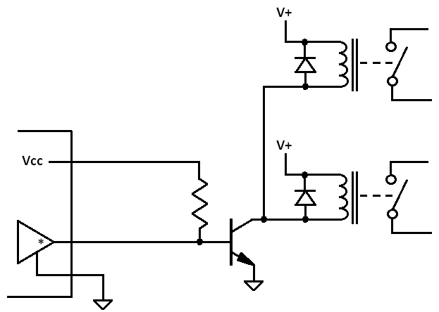
On the other hand if the rating of the output cannot meet the requirements of the relay coils then it will be required to buffer the output. This can be done various ways but here is one concept that can be used:

Component selection values need to be selected according to the current and voltage ratings of the output and the relay coils. Without detailed information being provided in the question selection cannot be specified here.
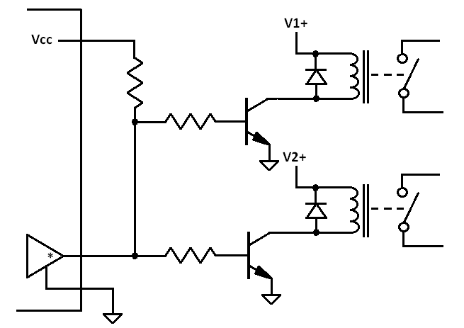
Note that it would be best to use a catch diode for each relay wired directly across the relay coil terminals.
Also note that if the two relay coils operate off different voltage levels then it would be required to have two separate driver circuits, one for each relay that are wired up as follows:

