Bounty Ended with 100 reputation awarded by CommunityBot
Added detail, further simulations
Source Link
tomnexus
  • 7.9k
  • 3
  • 20
  • 35
  • Cheap at under $0.10 for components (excluding the sense resistor)
  • No exotic components - Just one dual-1N4148 and some R and C.
  • Sensitive down to 50 mV AC, but errors will creep in
  • Very little part sensitivity, as long as the two diodes are matched and at the same temperature, or in the same package. Use 1% resistors.
  • Did I mention low costVery little frequency sensitivity
  • Very little temperature sensitivity, once compensated (not sensitive to tempco of capacitors)
  • Low component count
  • Also acts as a thermometer
  • Is also a thermometer. You need to regularly sample the other diode, to check the junction voltage due to the temperature alone.
  • Some calculations to be done in software, could be as simple as a subtraction.
  • No voltage gain. Vout drops by about 56270 mV with a 100240 mV (peakRMS) AC input
  • HighlySlightly non-linear response, DC voltage is not linear with AC voltage.
  • Probably slightly frequency sensitive (but then so is the rest of your circuit)
  • Probably has some other temperature sensitivity in the capacitors and resistors
  • Might have some part value sensitivity.

Achieving 5% resolution (at your operating point) will need about 10 bits in the A/D. 8 bits might be enough if you can change the A/D reference to (say) 1 V. Temperature calibration and non-linearity can be dealt with in software. Easy!

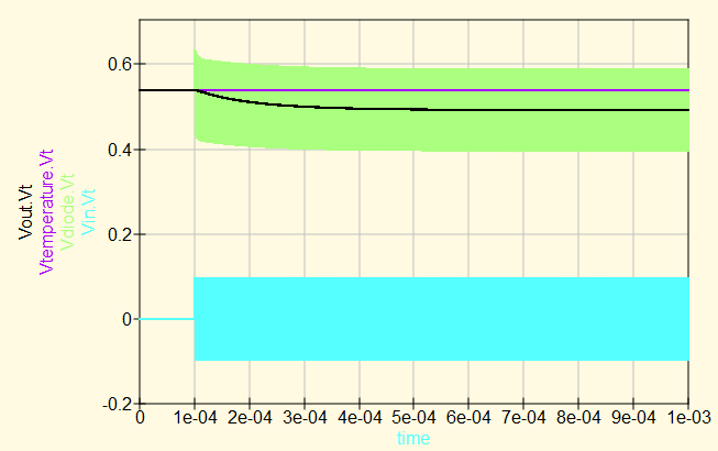
It works like this: Overall Voltages
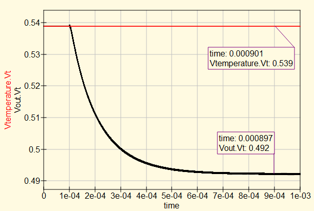
And plotting only the output DC voltages (here with a 100 mV peak AC signal): DC output voltages
Some simulations results varying parameters: StartingA quick investigation into the sensitivity of the circuit to parameter variations shows that once the equations are worked out, it should not be sensitive to temperature, frequency or changes in capacitance.

Starting with 2 MHz, 10 deg C, and 100 mV AC (Peak):

  • Base configuration: 539 (Vtemp) to 492 mV (Vout), 47 mV difference
  • 40 deg C : 449 to 406 mV, 42 mV No sensitivity to temperature (after subtraction)
  • 1.5 MHz : 539 to 492 mV, 47 mV. No sensitivity to Frequency
  • R1/R3 22K: 599 to 553 mV, 46 mV. No sensitivity to current, works well with more bias current. Source impedance of rectifier now drops too, it now stabilises in 0.3 ms instead of 0.6. R1 and R3 must still be matched...
  • 50 mV AC: 539 to 525 mV, 14 mV (practical lower limit of voltage)
  • 200 mV AC: 539 to 409 mV, 130 mV
  • 400339 mV AC: 539 to 227284 mV, 312255 mV (This is your operating point, 240 mV RMS)
  • 40 deg C 356 mV AC: 449 539 to 406268 mV, 42271 mV (operating point + 5%)

In Summary

  • 1.5 MHz : 539 to 492This circuit rectifies a 240 mV RMS AC voltage, 47to provide a 250 mV change in DC voltage.
  • If the AC voltage changes by 5%, the DC voltage changes by about 6%, a delta of 16 mV.
  • It has no sensitivity to Frequencytypical component tolerances, that would cause errors beyond 5%.
  • The exact DC value depends on temperature, but this is easily calibrated by comparison with a second diode in the same package, with the same bias but no AC.
  • A 12 bit A/D will give a resolution of about 0.25% per LSB, though in practice the resistor tolerance and diode matching will limit the accuracy long before this.
  • Cheap at under $0.10 for components (excluding the sense resistor)
  • No exotic components - Just one dual-1N4148 and some R and C.
  • Sensitive down to 50 mV AC, but errors will creep in
  • Very little part sensitivity, as long as the two diodes are matched and at the same temperature
  • Did I mention low cost
  • Low component count
  • Also acts as a thermometer
  • Is also a thermometer. You need to regularly sample the other diode, to check the junction voltage due to the temperature alone.
  • No voltage gain. Vout drops by about 56 mV with a 100 mV (peak) AC input
  • Highly non-linear, DC voltage is not linear with AC voltage.
  • Probably slightly frequency sensitive (but then so is the rest of your circuit)
  • Probably has some other temperature sensitivity in the capacitors and resistors
  • Might have some part value sensitivity.

Achieving 5% resolution (at your operating point) will need about 10 bits in the A/D. 8 bits might be enough if you can change the A/D reference to (say) 1 V. Temperature calibration and non-linearity can be dealt with in software. Easy!

It works like this: Overall Voltages

And plotting only the output DC voltages: DC output voltages

Some simulations results varying parameters: Starting with 2 MHz, 10 deg C, 100 mV AC (Peak):

  • Base configuration: 539 (Vtemp) to 492 mV (Vout), 47 mV difference
  • 50 mV AC: 539 to 525 mV, 14 mV
  • 200 mV AC: 539 to 409 mV, 130 mV
  • 400 mV AC: 539 to 227 mV, 312 mV
  • 40 deg C : 449 to 406 mV, 42 mV
  • 1.5 MHz : 539 to 492 mV, 47 mV, no sensitivity to Frequency
  • Cheap at under $0.10 for components (excluding the sense resistor)
  • No exotic components - Just one dual-1N4148 and some R and C.
  • Sensitive down to 50 mV AC, but errors will creep in
  • Very little part sensitivity, as long as the two diodes are matched and at the same temperature, or in the same package. Use 1% resistors.
  • Very little frequency sensitivity
  • Very little temperature sensitivity, once compensated (not sensitive to tempco of capacitors)
  • Low component count
  • Also acts as a thermometer
  • Is also a thermometer. You need to regularly sample the other diode, to check the junction voltage due to the temperature alone.
  • Some calculations to be done in software, could be as simple as a subtraction.
  • No voltage gain. Vout drops by about 270 mV with a 240 mV (RMS) AC input
  • Slightly non-linear response, DC voltage is not linear with AC voltage.

It works like this: Overall Voltages

And plotting only the output DC voltages (here with a 100 mV peak AC signal): DC output voltages

A quick investigation into the sensitivity of the circuit to parameter variations shows that once the equations are worked out, it should not be sensitive to temperature, frequency or changes in capacitance.

Starting with 2 MHz, 10 deg C, and 100 mV AC (Peak):

  • Base configuration: 539 (Vtemp) to 492 mV (Vout), 47 mV difference
  • 40 deg C : 449 to 406 mV, 42 mV No sensitivity to temperature (after subtraction)
  • 1.5 MHz : 539 to 492 mV, 47 mV. No sensitivity to Frequency
  • R1/R3 22K: 599 to 553 mV, 46 mV. No sensitivity to current, works well with more bias current. Source impedance of rectifier now drops too, it now stabilises in 0.3 ms instead of 0.6. R1 and R3 must still be matched...
  • 50 mV AC: 539 to 525 mV, 14 mV (practical lower limit of voltage)
  • 200 mV AC: 539 to 409 mV, 130 mV
  • 339 mV AC: 539 to 284 mV, 255 mV (This is your operating point, 240 mV RMS)
  • 356 mV AC: 539 to 268 mV, 271 mV (operating point + 5%)

In Summary

  • This circuit rectifies a 240 mV RMS AC voltage, to provide a 250 mV change in DC voltage.
  • If the AC voltage changes by 5%, the DC voltage changes by about 6%, a delta of 16 mV.
  • It has no sensitivity to typical component tolerances, that would cause errors beyond 5%.
  • The exact DC value depends on temperature, but this is easily calibrated by comparison with a second diode in the same package, with the same bias but no AC.
  • A 12 bit A/D will give a resolution of about 0.25% per LSB, though in practice the resistor tolerance and diode matching will limit the accuracy long before this.
more explanation
Source Link
tomnexus
  • 7.9k
  • 3
  • 20
  • 35

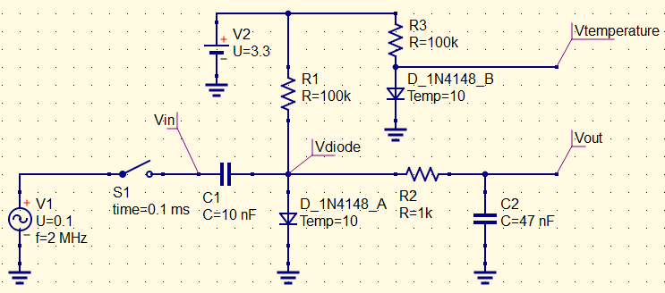
Here's an idea: A simple and rough solution by biasing a diode with a small current. It becomes non-linear and rectifies even quite small AC voltages.

I've drawn a possible circuit. You could refine all of the values to suit your exact requirements. D_A and D_B are a pair in one SOT23 case. R1 and R3 supply the bias current to the diodes, from a 3.3 V rail. R2 and C2 are a filter to reject the 2 MHz and provide a stable output; they have a time constant well under 1 ms, very little 2 MHz gets through. A larger R2 or larger C2 might be a good idea, depending on the speed of your control loop. To use this circuit you must sample and process both the rectified RF output, and the temperature sensing output, and do some calculations on the results. (The switch is only to allow me to see the difference between RF On and RF Off). Circuit Diagram

Advantages of this circuit:

  • Cheap at under $0.10 for components (excluding the sense resistor)
  • No exotic components - Just one dual-1N4148 and some R and C.
  • Sensitive down to 50 mV AC, but errors will creep in
  • Very little part sensitivity, as long as the two diodes are matched and at the same temperature
  • Did I mention low cost
  • Low component count
  • Also acts as a thermometer

Disadvantages:

  • Is also a thermometer. You need to regularly sample the other diode, to check the junction voltage due to the temperature alone.
  • No voltage gain. Vout drops by about 56 mV with a 100 mV (peak) AC input
  • Highly non-linear, DC voltage is not linear with AC voltage.
  • Probably slightly frequency sensitive (but then so is the rest of your circuit)
  • Probably has some other temperature sensitivity in the capacitors and resistors
  • Might have some part value sensitivity.

Achieving 5% resolution (at your operating point) will need about 10 bits in the A/D. 8 bits might be enough if you can change the A/D reference to (say) 1 V. Temperature calibration and non-linearity can be dealt with in software. Easy!

It works like this: Overall Voltages

And plotting only the output DC voltages: DC output voltages

BOM, (lowest cost reels from DigiKey)

  • 1 x pair of diodes: $ 0.01560
  • 3 x 100k resistors: $ 0.00093 each
  • 2 x Ceramic NP0 capacitors: $ 0.03914 each Total BOM: about $ 0.09667

Some simulations results varying parameters: Starting with 2 MHz, 10 deg C, 100 mV AC (Peak):

  • Base configuration: 539 (Vtemp) to 492 mV (Vout), 47 mV difference
  • 50 mV AC: 539 to 525 mV, 14 mV
  • 200 mV AC: 539 to 409 mV, 130 mV
  • 400 mV AC: 539 to 227 mV, 312 mV
  • 40 deg C : 449 to 406 mV, 42 mV
  • 1.5 MHz : 539 to 492 mV, 47 mV, no sensitivity to Frequency

Here's an idea: A simple and rough solution by biasing a diode with a small current. It becomes non-linear and rectifies even quite small AC voltages.

I've drawn a possible circuit. You could refine all of the values to suit your exact requirements. To use this circuit you must sample and process both the rectified RF output, and the temperature sensing output, and do some calculations on the results. (The switch is only to allow me to see the difference between RF On and RF Off). Circuit Diagram

Advantages of this circuit:

  • Cheap at under $0.10 for components (excluding the sense resistor)
  • No exotic components - Just one dual-1N4148 and some R and C.
  • Sensitive down to 50 mV AC, but errors will creep in
  • Very little part sensitivity, as long as the two diodes are matched and at the same temperature
  • Did I mention low cost
  • Low component count
  • Also acts as a thermometer

Disadvantages:

  • Is also a thermometer. You need to regularly sample the other diode, to check the junction voltage due to the temperature alone.
  • No voltage gain. Vout drops by about 56 mV with a 100 mV (peak) AC input
  • Highly non-linear, DC voltage is not linear with AC voltage.
  • Probably slightly frequency sensitive (but then so is the rest of your circuit)
  • Probably has some other temperature sensitivity in the capacitors and resistors
  • Might have some part value sensitivity.

Achieving 5% resolution (at your operating point) will need about 10 bits in the A/D. 8 bits might be enough if you can change the A/D reference to (say) 1 V. Temperature calibration and non-linearity can be dealt with in software. Easy!

It works like this: Overall Voltages

And plotting only the output DC voltages: DC output voltages

BOM, (lowest cost reels from DigiKey)

  • 1 x pair of diodes: $ 0.01560
  • 3 x 100k resistors: $ 0.00093 each
  • 2 x Ceramic NP0 capacitors: $ 0.03914 each Total BOM: about $ 0.09667

Some simulations results varying parameters: Starting with 2 MHz, 10 deg C, 100 mV AC (Peak):

  • Base configuration: 539 (Vtemp) to 492 mV (Vout), 47 mV difference
  • 50 mV AC: 539 to 525 mV, 14 mV
  • 200 mV AC: 539 to 409 mV, 130 mV
  • 400 mV AC: 539 to 227 mV, 312 mV
  • 40 deg C : 449 to 406 mV, 42 mV
  • 1.5 MHz : 539 to 492 mV, 47 mV, no sensitivity to Frequency

Here's an idea: A simple and rough solution by biasing a diode with a small current. It becomes non-linear and rectifies even quite small AC voltages.

I've drawn a possible circuit. You could refine all of the values to suit your exact requirements. D_A and D_B are a pair in one SOT23 case. R1 and R3 supply the bias current to the diodes, from a 3.3 V rail. R2 and C2 are a filter to reject the 2 MHz and provide a stable output; they have a time constant well under 1 ms, very little 2 MHz gets through. A larger R2 or larger C2 might be a good idea, depending on the speed of your control loop. To use this circuit you must sample and process both the rectified RF output, and the temperature sensing output, and do some calculations on the results. (The switch is only to allow me to see the difference between RF On and RF Off). Circuit Diagram

Advantages of this circuit:

  • Cheap at under $0.10 for components (excluding the sense resistor)
  • No exotic components - Just one dual-1N4148 and some R and C.
  • Sensitive down to 50 mV AC, but errors will creep in
  • Very little part sensitivity, as long as the two diodes are matched and at the same temperature
  • Did I mention low cost
  • Low component count
  • Also acts as a thermometer

Disadvantages:

  • Is also a thermometer. You need to regularly sample the other diode, to check the junction voltage due to the temperature alone.
  • No voltage gain. Vout drops by about 56 mV with a 100 mV (peak) AC input
  • Highly non-linear, DC voltage is not linear with AC voltage.
  • Probably slightly frequency sensitive (but then so is the rest of your circuit)
  • Probably has some other temperature sensitivity in the capacitors and resistors
  • Might have some part value sensitivity.

Achieving 5% resolution (at your operating point) will need about 10 bits in the A/D. 8 bits might be enough if you can change the A/D reference to (say) 1 V. Temperature calibration and non-linearity can be dealt with in software. Easy!

It works like this: Overall Voltages

And plotting only the output DC voltages: DC output voltages

BOM, (lowest cost reels from DigiKey)

  • 1 x pair of diodes: $ 0.01560
  • 3 x 100k resistors: $ 0.00093 each
  • 2 x Ceramic NP0 capacitors: $ 0.03914 each Total BOM: about $ 0.09667

Some simulations results varying parameters: Starting with 2 MHz, 10 deg C, 100 mV AC (Peak):

  • Base configuration: 539 (Vtemp) to 492 mV (Vout), 47 mV difference
  • 50 mV AC: 539 to 525 mV, 14 mV
  • 200 mV AC: 539 to 409 mV, 130 mV
  • 400 mV AC: 539 to 227 mV, 312 mV
  • 40 deg C : 449 to 406 mV, 42 mV
  • 1.5 MHz : 539 to 492 mV, 47 mV, no sensitivity to Frequency
added 29 characters in body
Source Link
tomnexus
  • 7.9k
  • 3
  • 20
  • 35

Here's an idea: A simple and rough solution by biasing a diode with a small current. It becomes non-linear and rectifies even quite small AC voltages.

I've drawn a possible circuit. You could refine all of the values to suit your exact requirements. To use this circuit you must sample and process both the rectified RF output, and the temperature sensing output, and do some calculations on the results. (The switch is only to allow me to see the difference between RF On and RF Off). Circuit Diagram

Advantages of this circuit:

  • Cheap at under $0.10 for components (excluding the sense resistor)
  • No exotic components - Just one dual-1N4148 and some R and C.
  • Sensitive down to 50 mV AC, but errors will creep in
  • Very little part sensitivity, as long as the two diodes are matched and at the same temperature
  • Did I mention low cost
  • Low component count
  • Also acts as a thermometer

Disadvantages:

  • Is also a thermometer You. You need to regularly sample the other diode, to check the junction voltage without RFdue to the temperature alone.
  • SmallNo voltage changegain. Vout drops by about 56 mV with a 71100 mV (peak) AC input
  • Highly non-linear, DC voltage is not linear with AC voltage.
  • Probably slightly frequency sensitive (but then so is the rest of your circuit)
  • Probably has some other temperature sensitivity in the capacitors and resistors
  • Might have some part value sensitivity.

Achieving 5% resolution (at your operating point) will need about 10 bits in the A/D. 8 bits might be enough if you can change the A/D reference to (say) 1 V. Temperature calibration and non-linearity can be dealt with in software. Easy!

It works like this: Overall Voltages

And plotting only the output DC voltages: DC output voltages

BOM, (lowest cost reels from DigiKey)

  • 1 x pair of diodes: $ 0.01560
  • 3 x 100k resistors: $ 0.00093 each
  • 2 x Ceramic NP0 capacitors: $ 0.03914 each Total BOM: about $ 0.09667

Some simulations results varying parameters: Starting with 2 MHz, 10 deg C, 100 mV AC (P-PPeak):

  • Base configuration: 539 (Vtemp) to 492 mV (Vout), 47 mV difference
  • 50 mV AC: 539 to 525 mV, 14 mV
  • 200 mV AC: 539 to 409 mV, 130 mV
  • 400 mV AC: 539 to 227 mV, 312 mV
  • 40 deg C : 449 to 406 mV, 42 mV
  • 1.5 MHz : 539 to 492 mV, 47 mV, no sensitivity to Frequency

Here's an idea: A simple and rough solution by biasing a diode with a small current. It becomes non-linear and rectifies even quite small AC voltages.

I've drawn a possible circuit. You could refine all of the values to suit your exact requirements. To use this circuit you must sample and process both the rectified RF output, and the temperature sensing output, and do some calculations on the results. (The switch is only to allow me to see the difference between RF On and RF Off). Circuit Diagram

Advantages of this circuit:

  • Cheap at under $0.10 for components (excluding the sense resistor)
  • No exotic components - Just one dual-1N4148 and some R and C.
  • Sensitive down to 50 mV AC, but errors will creep in
  • Very little part sensitivity, as long as the two diodes are matched and at the same temperature
  • Did I mention low cost
  • Low component count
  • Also acts as a thermometer

Disadvantages:

  • Is also a thermometer You need to regularly sample the other diode, to check the voltage without RF
  • Small voltage change. Vout drops by about 56 mV with a 71 mV AC input
  • Highly non-linear, DC voltage is not linear with AC voltage.
  • Probably slightly frequency sensitive (but then so is the rest of your circuit)
  • Probably has some other temperature sensitivity in the capacitors and resistors
  • Might have some part value sensitivity.

Achieving 5% resolution (at your operating point) will need about 10 bits in the A/D. 8 bits might be enough if you can change the A/D reference to (say) 1 V. Temperature calibration and non-linearity can be dealt with in software. Easy!

It works like this: Overall Voltages

And plotting only the output DC voltages: DC output voltages

BOM, (lowest cost reels from DigiKey)

  • 1 x pair of diodes: $ 0.01560
  • 3 x 100k resistors: $ 0.00093 each
  • 2 x Ceramic NP0 capacitors: $ 0.03914 each Total BOM: about $ 0.09667

Some simulations results varying parameters: Starting with 2 MHz, 10 deg C, 100 mV AC (P-P):

  • Base configuration: 539 (Vtemp) to 492 mV (Vout), 47 mV difference
  • 50 mV AC: 539 to 525 mV, 14 mV
  • 200 mV AC: 539 to 409 mV, 130 mV
  • 400 mV AC: 539 to 227 mV, 312 mV
  • 40 deg C : 449 to 406 mV, 42 mV
  • 1.5 MHz : 539 to 492 mV, 47 mV, no sensitivity to Frequency

Here's an idea: A simple and rough solution by biasing a diode with a small current. It becomes non-linear and rectifies even quite small AC voltages.

I've drawn a possible circuit. You could refine all of the values to suit your exact requirements. To use this circuit you must sample and process both the rectified RF output, and the temperature sensing output, and do some calculations on the results. (The switch is only to allow me to see the difference between RF On and RF Off). Circuit Diagram

Advantages of this circuit:

  • Cheap at under $0.10 for components (excluding the sense resistor)
  • No exotic components - Just one dual-1N4148 and some R and C.
  • Sensitive down to 50 mV AC, but errors will creep in
  • Very little part sensitivity, as long as the two diodes are matched and at the same temperature
  • Did I mention low cost
  • Low component count
  • Also acts as a thermometer

Disadvantages:

  • Is also a thermometer. You need to regularly sample the other diode, to check the junction voltage due to the temperature alone.
  • No voltage gain. Vout drops by about 56 mV with a 100 mV (peak) AC input
  • Highly non-linear, DC voltage is not linear with AC voltage.
  • Probably slightly frequency sensitive (but then so is the rest of your circuit)
  • Probably has some other temperature sensitivity in the capacitors and resistors
  • Might have some part value sensitivity.

Achieving 5% resolution (at your operating point) will need about 10 bits in the A/D. 8 bits might be enough if you can change the A/D reference to (say) 1 V. Temperature calibration and non-linearity can be dealt with in software. Easy!

It works like this: Overall Voltages

And plotting only the output DC voltages: DC output voltages

BOM, (lowest cost reels from DigiKey)

  • 1 x pair of diodes: $ 0.01560
  • 3 x 100k resistors: $ 0.00093 each
  • 2 x Ceramic NP0 capacitors: $ 0.03914 each Total BOM: about $ 0.09667

Some simulations results varying parameters: Starting with 2 MHz, 10 deg C, 100 mV AC (Peak):

  • Base configuration: 539 (Vtemp) to 492 mV (Vout), 47 mV difference
  • 50 mV AC: 539 to 525 mV, 14 mV
  • 200 mV AC: 539 to 409 mV, 130 mV
  • 400 mV AC: 539 to 227 mV, 312 mV
  • 40 deg C : 449 to 406 mV, 42 mV
  • 1.5 MHz : 539 to 492 mV, 47 mV, no sensitivity to Frequency
small corrections
Source Link
tomnexus
  • 7.9k
  • 3
  • 20
  • 35
Loading
Source Link
tomnexus
  • 7.9k
  • 3
  • 20
  • 35
Loading