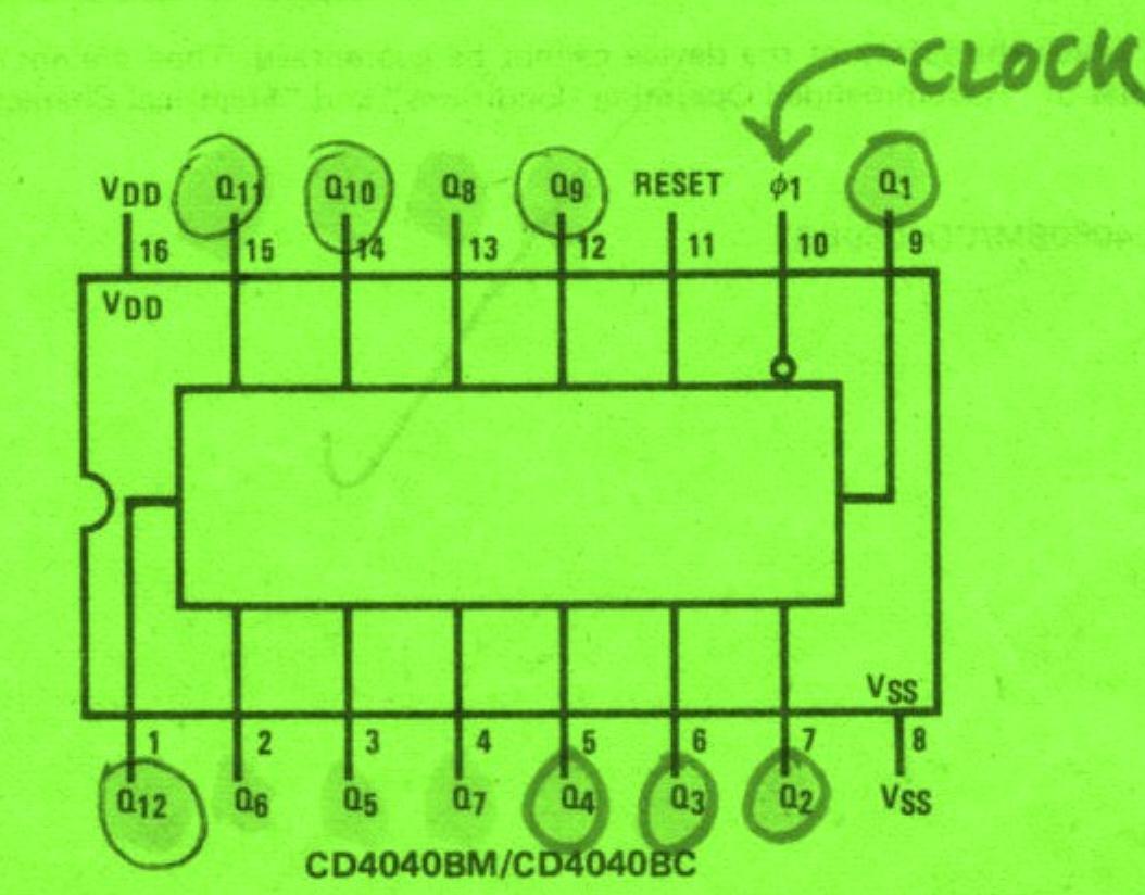
I have been having problems of a similar nature using a CD4040 being fed ok with a 2Hz clock from a CD4060 set up with a 32,768 Hz xtal. The CD4060 provides a Q14 output. I was trying to get the CD4040 to divide by 120 in order to get a one minute pulse. So I diode ANDED Q4 thru Q7 for all ones with a 22k pullup and fed the ANDED signal to the reset. Q7 NEVER WENT HIGH.
I I took out this circuit and strapped the reset to ground. Note that on ALL the diagrams I have, Q7 appears on pin 4. So I expected to see, and measured the signal periods on all Qs up to Q7. Q7 was now toggling OK. All was well up to Q6 which showed 32 second period. BUT Q7 on pin 4 measured 128 seconds! I then guessed that probably the circuit diagram data was wrong. And reading your report above today stating NXP data shows Q7 at pin 13, confirms that SOME DATA SHEETS HAVE AT LEAST Q7 WITH THE INCORRECT PIN NUMBER. As stated I believe Q1 to Q6 are OK. I will now search for this NXP data sheet to confirm.I will retest my circuit using pin 13.
UPDATE
I have checked my old National Semiconductor datasheet, and it seems they have marked Q0 as Q1, Q1 as Q2, Q2 as Q3 etc. So Q7 actually is on pin 13! I have not checked the other pins. This appears to offer some clue as to why YOUR reset circuit didn't work.

