added 594 characters in body
Source Link

I am trying to create a project based on TI chip BQ78412 (Pb-Acid Battery State-of-Charge Indicator With Run-Time Display). There is an evaluation board whose schematic is published in this pdf on page 18.

I am struggling to understand why part of this schematic works (see below the one in question).

My main problem is that the VCC is 3.3V (and all signals) but the LEDs are switched on/off by the transistor through 12 V from a separate battery that has a common ground with the rest of the schematic. I assume that when I have logical 0 on the output pins of the IC the LED will be on as it will be connected to ground. But if I have logical 1, it would be still 3.3V so I will have effective voltage of 8,7V that would be sufficient for the LEDs to be on - the current would be about 66 mA! So I guess I am missing something very basic and important...

I also don't get why the current limiting resistors for the LEDs are 100 ohm - the current should be 20 mA (limited by the IC) and the forward voltage should be 2,1V if I am not wrong (see datasheet for SML-LX0603YW-TR) so according to Mr. Ohm it should be around 495 Ohm.
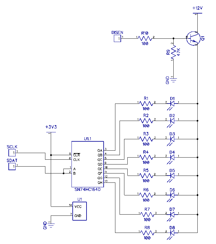
enter image description here

Regards,

Evgeni

EDIT: In my question I have made some false assumptions due to lack of knowledge and experience:

  1. I didn't recognize that the transistor is acting as emitter follower which was a very important fact.
  2. I have also assumed that the driving current of the serial shift register is max 20 mA rather than 5 mA - I am still not sure how to interpret the data sheet - I'l ask a separate question on this.
  3. I have assumed that 1-3 mA would be quite insufficient for the LED to emit light as it's forward current according to the data sheet is 20 mA.
  4. I have also underestimated the HC164 Vlow assuming that it is always 0 V which apparently is not true either.

I am trying to create a project based on TI chip BQ78412 (Pb-Acid Battery State-of-Charge Indicator With Run-Time Display). There is an evaluation board whose schematic is published in this pdf on page 18.

I am struggling to understand why part of this schematic works (see below the one in question).

My main problem is that the VCC is 3.3V (and all signals) but the LEDs are switched on/off by the transistor through 12 V from a separate battery that has a common ground with the rest of the schematic. I assume that when I have logical 0 on the output pins of the IC the LED will be on as it will be connected to ground. But if I have logical 1, it would be still 3.3V so I will have effective voltage of 8,7V that would be sufficient for the LEDs to be on - the current would be about 66 mA! So I guess I am missing something very basic and important...

I also don't get why the current limiting resistors for the LEDs are 100 ohm - the current should be 20 mA (limited by the IC) and the forward voltage should be 2,1V if I am not wrong (see datasheet for SML-LX0603YW-TR) so according to Mr. Ohm it should be around 495 Ohm.

enter image description here

Regards,

Evgeni

EDIT: In my question I have made some false assumptions due to lack of knowledge and experience:

  1. I didn't recognize that the transistor is acting as emitter follower which was a very important fact.
  2. I have also assumed that the driving current of the serial shift register is max 20 mA rather than 5 mA - I am still not sure how to interpret the data sheet - I'l ask a separate question on this.
  3. I have assumed that 1-3 mA would be quite insufficient for the LED to emit light as it's forward current according to the data sheet is 20 mA.
  4. I have also underestimated the HC164 Vlow assuming that it is always 0 V which apparently is not true either.
sdeas
Source Link

I am trying to create a project based on TI chip BQ78412 (Pb-Acid Battery State-of-Charge Indicator With Run-Time Display). There is an evaluation board whose schematic is published in this pdf on page 18.

I am struggling to understand why part of this schematic works (see below the one in question).

My main problem is that the VCC is 3.3V (and all signals) but the LEDs are switched on/off by the transistor through 12 V from a separate battery that has a common ground with the rest of the schematic. I assume that when I have logical 0 on the output pins of the IC the LED will be on as it will be connected to ground. But if I have logical 1, it would be still 3.3V so I will have effective voltage of 8,7V that would be sufficient for the LEDs to be on - the current would be about 66 mA! So I guess I am missing something very basic and important...

I also don't get why the current limiting resistors for the LEDs are 100 ohm - the current should be 20 mA (limited by the IC) and the forward voltage should be 2,1V if I am not wrong (see datasheet for SML-LX0603YW-TR) so according to Mr. Ohm it should be around 495 Ohm.

enter image description here

Regards,

Evgeni

Source Link

Driving LED using SN74HC164 and transistor. Apparently this schematic works but I don't understand why!

I am trying to create a project based on TI chip BQ78412 (Pb-Acid Battery State-of-Charge Indicator With Run-Time Display). There is an evaluation board whose schematic is published in this pdf on page 18.

I am struggling to understand why part of this schematic works (see below the one in question).

My main problem is that the VCC is 3.3V (and all signals) but the LEDs are switched on/off by the transistor through 12 V from a separate battery that has a common ground with the rest of the schematic. I assume that when I have logical 0 on the output pins of the IC the LED will be on as it will be connected to ground. But if I have logical 1, it would be still 3.3V so I will have effective voltage of 8,7V that would be sufficient for the LEDs to be on - the current would be about 66 mA! So I guess I am missing something very basic and important...

I also don't get why the current limiting resistors for the LEDs are 100 ohm - the current should be 20 mA (limited by the IC) and the forward voltage should be 2,1V if I am not wrong (see datasheet for SML-LX0603YW-TR) so according to Mr. Ohm it should be around 495 Ohm.

enter image description here

Regards,

Evgeni