Beautify, MathJaX
Source Link
Grabul
  • 3.5k
  • 1
  • 15
  • 21

Take this schematic :
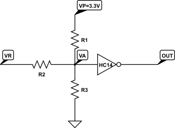
schematic

simulate this circuit – Schematic created using CircuitLab

Playing with Ohm's law, you get : R3.R1.VR+R3.R2.VP=(R1.R2+R1.R3+R2.R3).VA\$R_{3} \times R_{1}\times V_{R}+R_{3} \times R_{2} \times V_{P} = (R_{1} \times R_{2}+R_{1} \times R_{3}+R_{2} \times R_{3}) \times V_{A}\$

If you set VR=0, VA shall be equal to VP/2=1.65V. You get :

R1=(R2.R3)/(R3+R2)\$R_{1} = \dfrac{R_{2} \times R_{3}}{R_{3}+R_{2}} \$ (or R1=R2R1 = R2 parallel with R3)

For Thethe maximum input voltage, 5V, VA=VP :

R3=R2.VP/(VRmax-VP) = R2 * 3.3 / (5-3\$R_{3} = \dfrac{R_{2} \times V_{P}}{V_{Rmax} - V_{P}} = \dfrac{R_{2} \times 3.3}{5-3.3}\$


So.3)

With standard resistor values, you can pick : R1=10k, R2=16k, R3=30kR1=10k, R2=16k, R3=30k

The gate should have a Schmidt trigger, and support any intermediate voltage at its input, for example an HC14. If you are afraid of exceeding the +5V/-5V range, you can add clamping diodes at the input of the inverter.

Take this schematic :

schematic

simulate this circuit – Schematic created using CircuitLab

Playing with Ohm's law, you get : R3.R1.VR+R3.R2.VP=(R1.R2+R1.R3+R2.R3).VA

If you set VR=0, VA shall be equal to VP/2=1.65V. You get :

R1=(R2.R3)/(R3+R2) (or R1=R2 parallel with R3)

For The maximum input voltage, 5V, VA=VP :

R3=R2.VP/(VRmax-VP) = R2 * 3.3 / (5-3.3)

With standard resistor values, you can pick : R1=10k, R2=16k, R3=30k

The gate should have a Schmidt trigger, and support any intermediate voltage at its input, for example an HC14.

Take this schematic :

schematic

simulate this circuit – Schematic created using CircuitLab

Playing with Ohm's law, you get : \$R_{3} \times R_{1}\times V_{R}+R_{3} \times R_{2} \times V_{P} = (R_{1} \times R_{2}+R_{1} \times R_{3}+R_{2} \times R_{3}) \times V_{A}\$

If you set VR=0, VA shall be equal to VP/2=1.65V. You get :

\$R_{1} = \dfrac{R_{2} \times R_{3}}{R_{3}+R_{2}} \$ (or R1 = R2 parallel with R3)

For the maximum input voltage, 5V, VA=VP :

\$R_{3} = \dfrac{R_{2} \times V_{P}}{V_{Rmax} - V_{P}} = \dfrac{R_{2} \times 3.3}{5-3.3}\$


So.

With standard resistor values, you can pick : R1=10k, R2=16k, R3=30k

The gate should have a Schmidt trigger, and support any intermediate voltage at its input, for example an HC14. If you are afraid of exceeding the +5V/-5V range, you can add clamping diodes at the input of the inverter.

Source Link
Grabul
  • 3.5k
  • 1
  • 15
  • 21

Take this schematic :

schematic

simulate this circuit – Schematic created using CircuitLab

Playing with Ohm's law, you get : R3.R1.VR+R3.R2.VP=(R1.R2+R1.R3+R2.R3).VA

If you set VR=0, VA shall be equal to VP/2=1.65V. You get :

R1=(R2.R3)/(R3+R2) (or R1=R2 parallel with R3)

For The maximum input voltage, 5V, VA=VP :

R3=R2.VP/(VRmax-VP) = R2 * 3.3 / (5-3.3)

With standard resistor values, you can pick : R1=10k, R2=16k, R3=30k

The gate should have a Schmidt trigger, and support any intermediate voltage at its input, for example an HC14.