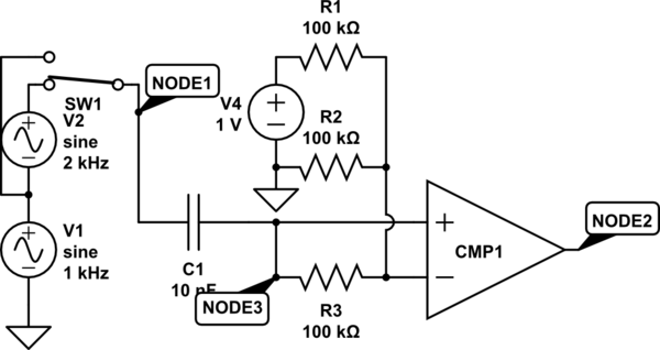
One thing you don't mention is whether the square wave needs to be square even if the sine wave may be distorted. I don't think a Schmidt trigger is needed here since the sine wave's dV/dt will be at its maximum near the switching point. A simple way to achieve a reasonable result would be:


simulate this circuitsimulate this circuit – Schematic created using CircuitLab
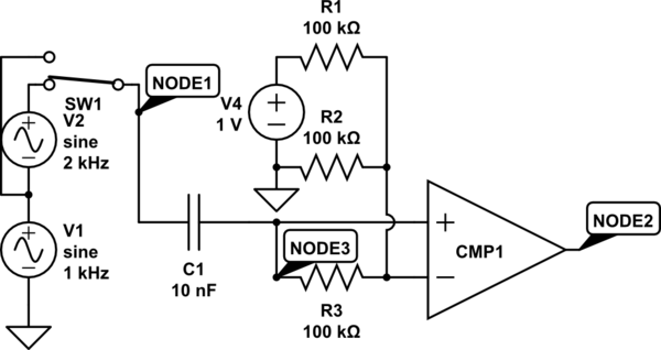
Once the circuit "warms up", it should give a 50%-duty-cycle square wave when given a sine-wave input. If given a distorted wave, however (in "build" mode, click "SW1" and click "properties" to switch its state) the output may not be quite square. There are other ways of setting up the circuit to ensure a 50%-duty-cycle output even in the presence of even harmonic distortion on the input, but this approach is nice and simple. The voltage divider for the comparator's reference voltage may be set to any convenient value; the duty cycle of the input is controlled by the symmetry of the input, rather than resistance ratios; designs to yield a symmetrical output when given a distorted input would have a duty cycle set by a resistance ratio.
