Tweeted twitter.com/#!/StackElectronix/status/589851304090083329
deleted 5 characters in body
Source Link
nape
  • 31
  • 3

my mind needs refreshing so could someone please help explaining analysis of this circuit.

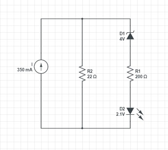
It is used for testing a current regulator (LED driver circuit) ('I' in the image). The regulator current is divided between a resistor and a series connection of a Zener, resistor and a LED. If the LEDD2 illuminates the current regulator is supposed to pass the test.

Majority of the current of course flows through the single resistor, but I don't understand the equation how it is exactly divided between the two circuit branches. I would like to replicate this circuit for testing a current source with different amperage, and thus would need the equation how to select proper values for Zener and the resistors.

Many thanks in advance.
enter image description here

my mind needs refreshing so could someone please help explaining analysis of this circuit.

It is used for testing a current regulator (LED driver circuit) ('I' in the image). The regulator current is divided between a resistor and a series connection of a Zener, resistor and a LED. If the LED illuminates the current regulator is supposed to pass the test.

Majority of the current of course flows through the single resistor, but I don't understand the equation how it is exactly divided between the two circuit branches. I would like to replicate this circuit for testing a current source with different amperage, and thus would need the equation how to select proper values for Zener and the resistors.

Many thanks in advance.

enter image description here

my mind needs refreshing so could someone please help explaining analysis of this circuit.

It is used for testing a current regulator (LED driver circuit) ('I' in the image). The regulator current is divided between a resistor and a series connection of a Zener, resistor and a LED. If D2 illuminates the current regulator is supposed to pass the test.

Majority of the current of course flows through the single resistor, but I don't understand the equation how it is exactly divided between the two circuit branches. I would like to replicate this circuit for testing a current source with different amperage, and thus would need the equation how to select proper values for Zener and the resistors.

Many thanks in advance.

enter image description here

Source Link
nape
  • 31
  • 3

Please explain the circuit (current regulator test circuit with Zener diode)

my mind needs refreshing so could someone please help explaining analysis of this circuit.

It is used for testing a current regulator (LED driver circuit) ('I' in the image). The regulator current is divided between a resistor and a series connection of a Zener, resistor and a LED. If the LED illuminates the current regulator is supposed to pass the test.

Majority of the current of course flows through the single resistor, but I don't understand the equation how it is exactly divided between the two circuit branches. I would like to replicate this circuit for testing a current source with different amperage, and thus would need the equation how to select proper values for Zener and the resistors.

Many thanks in advance.

enter image description here