added 36 characters in body
Source Link
Mister Mystère
  • 9.8k
  • 6
  • 56
  • 89

The voltage applied to the load does not magically switch from 230V to 400V when you remove the neutral. The wiring configuration between the supply and the load, called "coupling", determines whether 230V or 400V is applied across the load(s).

Take a three phase power supply. Each phase will be 230V when taking the neutral as a reference. Because each phase is phased out by 120°, the voltage between any two phase is 400V. Here is the quick demonstration for $U_{21}=V_2-V_1$; same goes for the others. $$U_{21}=V_2-V_1=230\cos(\omega t)-230\cos(\omega t+2\pi/3)$$ $$=230\left(\cos(\omega t)-\left( \cos(\omega t)\cos(2\pi/3)-sin(\omega t)\sin(2\pi/3)\right)\right)$$ $$=230\left(\cos(\omega t) +\frac{1}{2}\cos(\omega t)+\frac{\sqrt{3}}{2}\sin(\omega t)\right)$$ $$=230\left(\frac{3}{2}\cos(\omega t)+\frac{\sqrt{3}}{2}\sin(\omega t)\right)$$ $$=230\left( \sqrt{3}\sin(\omega t +\alpha)\right), \alpha=tan^{-1}(\sqrt{3})$$ (refer to trigonometric identities) As you can see, the amplitude of the phase to phase voltage is $230\sqrt{3}$ (note that 230V is valid only in certain countries, but the same logic is applicable otherwise), or 400V. This can also be verified using phasor diagrams, as used below to illustrate coupling.

Here is the quick demonstration for $U_{21}=V_2-V_1$; same goes for the others. $$U_{21}=V_2-V_1=230\cos(\omega t)-230\cos(\omega t+2\pi/3)$$ $$=230\left(\cos(\omega t)-\left( \cos(\omega t)\cos(2\pi/3)-sin(\omega t)\sin(2\pi/3)\right)\right)$$ $$=230\left(\cos(\omega t) +\frac{1}{2}\cos(\omega t)+\frac{\sqrt{3}}{2}\sin(\omega t)\right)$$ $$=230\left(\frac{3}{2}\cos(\omega t)+\frac{\sqrt{3}}{2}\sin(\omega t)\right)$$ $$=230\left( \sqrt{3}\sin(\omega t +\alpha)\right), \alpha=tan^{-1}(\sqrt{3})$$ (refer to trigonometric identities) As you can see, the amplitude of the phase to phase voltage is $230\sqrt{3}$ (note that 230V is valid only in certain countries, but the same logic is applicable otherwise), or 400V. This can also be verified using phasor diagrams, as used below to illustrate coupling.

Now, it happens that there is 400V between the phases. Nothing prevents you from connecting a load across the phases instead of between a phase and the neutral. This is actually the origin of coupling: if you have a 3 phase load, say a motor, you can connect each winding across phases, or across one phase and the neutral (you could even do a mixture, but it is not recommended in many cases as the load voltages would be unbalanced). If the load is connected across phases AND assuming the windings are identical, if you do the maths you'll notice there is no current flowing through the neutral which explains why it is sometimes not present.

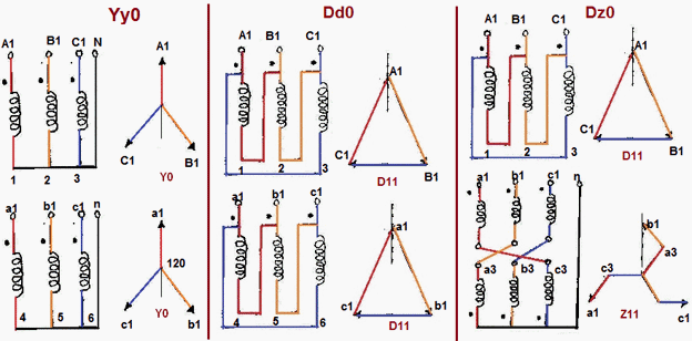
The configuration in which the load is connected across phases is called Delta, from the configuration of the windings on a schematic (and the shape of the phasor diagram). The configuration in which the load is connected across phase and neutral is called Y or Star, for the same reasons. Note that this configuration can be done on the supply side, that's the pair of both configurations that gives you the coupling, e.g. DY or YY. Here are examples of common couplings with their phasor diagram (on which the magnitude of vectors is the RMS voltage and the angles represent phase difference. From there it is standard vector geometry. The origin of vectors is irrelevant.): enter image description here (source)
In a nutshell, when neutral is not wired between the equipment and the supply there is no way that the loads are connected between phase and neutral - they must be connected between phases, which is 400V. If the neutral is here, you have the choice between 230V across loads, or 400V depending on the wiring. In the latter case, removing the neutral will have negligible effects as close to no current flows in it. In the former case, the loads will be shut down as the circuit has been open.

The voltage applied to the load does not magically switch from 230V to 400V when you remove the neutral. The wiring configuration between the supply and the load, called "coupling", determines whether 230V or 400V is applied across the load(s).

Take a three phase power supply. Each phase will be 230V when taking the neutral as a reference. Because each phase is phased out by 120°, the voltage between any two phase is 400V. Here is the quick demonstration for $U_{21}=V_2-V_1$; same goes for the others. $$U_{21}=V_2-V_1=230\cos(\omega t)-230\cos(\omega t+2\pi/3)$$ $$=230\left(\cos(\omega t)-\left( \cos(\omega t)\cos(2\pi/3)-sin(\omega t)\sin(2\pi/3)\right)\right)$$ $$=230\left(\cos(\omega t) +\frac{1}{2}\cos(\omega t)+\frac{\sqrt{3}}{2}\sin(\omega t)\right)$$ $$=230\left(\frac{3}{2}\cos(\omega t)+\frac{\sqrt{3}}{2}\sin(\omega t)\right)$$ $$=230\left( \sqrt{3}\sin(\omega t +\alpha)\right), \alpha=tan^{-1}(\sqrt{3})$$ (refer to trigonometric identities) As you can see, the amplitude of the phase to phase voltage is $230\sqrt{3}$ (note that 230V is valid only in certain countries, but the same logic is applicable otherwise), or 400V. This can also be verified using phasor diagrams, as used below to illustrate coupling.

Now, it happens that there is 400V between the phases. Nothing prevents you from connecting a load across the phases instead of between a phase and the neutral. This is actually the origin of coupling: if you have a 3 phase load, say a motor, you can connect each winding across phases, or across one phase and the neutral (you could even do a mixture, but it is not recommended in many cases as the load voltages would be unbalanced). If the load is connected across phases AND assuming the windings are identical, if you do the maths you'll notice there is no current flowing through the neutral which explains why it is sometimes not present.

The configuration in which the load is connected across phases is called Delta, from the configuration of the windings on a schematic (and the shape of the phasor diagram). The configuration in which the load is connected across phase and neutral is called Y or Star, for the same reasons. Note that this configuration can be done on the supply side, that's the pair of both configurations that gives you the coupling, e.g. DY or YY. Here are examples of common couplings with their phasor diagram (on which the magnitude of vectors is the RMS voltage and the angles represent phase difference. From there it is standard vector geometry. The origin of vectors is irrelevant.): enter image description here (source)

In a nutshell, when neutral is not wired between the equipment and the supply there is no way that the loads are connected between phase and neutral - they must be connected between phases, which is 400V. If the neutral is here, you have the choice between 230V across loads, or 400V depending on the wiring. In the latter case, removing the neutral will have negligible effects as close to no current flows in it. In the former case, the loads will be shut down as the circuit has been open.

The voltage applied to the load does not magically switch from 230V to 400V when you remove the neutral. The wiring configuration between the supply and the load, called "coupling", determines whether 230V or 400V is applied across the load(s).

Take a three phase power supply. Each phase will be 230V when taking the neutral as a reference. Because each phase is phased out by 120°, the voltage between any two phase is 400V.

Here is the quick demonstration for $U_{21}=V_2-V_1$; same goes for the others. $$U_{21}=V_2-V_1=230\cos(\omega t)-230\cos(\omega t+2\pi/3)$$ $$=230\left(\cos(\omega t)-\left( \cos(\omega t)\cos(2\pi/3)-sin(\omega t)\sin(2\pi/3)\right)\right)$$ $$=230\left(\cos(\omega t) +\frac{1}{2}\cos(\omega t)+\frac{\sqrt{3}}{2}\sin(\omega t)\right)$$ $$=230\left(\frac{3}{2}\cos(\omega t)+\frac{\sqrt{3}}{2}\sin(\omega t)\right)$$ $$=230\left( \sqrt{3}\sin(\omega t +\alpha)\right), \alpha=tan^{-1}(\sqrt{3})$$ (refer to trigonometric identities) As you can see, the amplitude of the phase to phase voltage is $230\sqrt{3}$ (note that 230V is valid only in certain countries, but the same logic is applicable otherwise), or 400V. This can also be verified using phasor diagrams, as used below to illustrate coupling.

Now, it happens that there is 400V between the phases. Nothing prevents you from connecting a load across the phases instead of between a phase and the neutral. This is actually the origin of coupling: if you have a 3 phase load, say a motor, you can connect each winding across phases, or across one phase and the neutral (you could even do a mixture, but it is not recommended in many cases as the load voltages would be unbalanced). If the load is connected across phases AND assuming the windings are identical, if you do the maths you'll notice there is no current flowing through the neutral which explains why it is sometimes not present.

The configuration in which the load is connected across phases is called Delta, from the configuration of the windings on a schematic (and the shape of the phasor diagram). The configuration in which the load is connected across phase and neutral is called Y or Star, for the same reasons. Note that this configuration can be done on the supply side, that's the pair of both configurations that gives you the coupling, e.g. DY or YY. Here are examples of common couplings with their phasor diagram (on which the magnitude of vectors is the RMS voltage and the angles represent phase difference. From there it is standard vector geometry. The origin of vectors is irrelevant.): enter image description here (source)

In a nutshell, when neutral is not wired between the equipment and the supply there is no way that the loads are connected between phase and neutral - they must be connected between phases, which is 400V. If the neutral is here, you have the choice between 230V across loads, or 400V depending on the wiring. In the latter case, removing the neutral will have negligible effects as close to no current flows in it. In the former case, the loads will be shut down as the circuit has been open.

added 65 characters in body
Source Link
Mister Mystère
  • 9.8k
  • 6
  • 56
  • 89

The voltage applied to the load does not magically switch from 230V to 400V when you remove the neutral. The wiring configuration between the supply and the load, called "coupling", determines whether 230V or 400V is applied across the load(s).

Take a three phase power supply. Each phase will be 230V when taking the neutral as a reference. Because each phase is phased out by 120°, the voltage between any two phase is 400V. Here is the quick demonstration for $U_{21}=V_2-V_1$; same goes for the others. $$U_{21}=V_2-V_1=230\cos(\omega t)-230\cos(\omega t+2\pi/3)$$ $$=230\left(\cos(\omega t)-\left( \cos(\omega t)\cos(2\pi/3)-sin(\omega t)\sin(2\pi/3)\right)\right)$$ $$=230\left(\cos(\omega t) +\frac{1}{2}\cos(\omega t)+\frac{\sqrt{3}}{2}\sin(\omega t)\right)$$ $$=230\left(\frac{3}{2}\cos(\omega t)+\frac{\sqrt{3}}{2}\sin(\omega t)\right)$$ $$=230\left( \sqrt{3}\sin(\omega t +\alpha)\right), \alpha=tan^{-1}(\sqrt{3})$$ (refer to trigonometric identities) As you can see, the amplitude of the phase to phase voltage is $230\sqrt{3}$ (note that 230V is valid only in certain countries, but the same logic is applicable otherwise), or 400V. This can also be verified using phasor diagrams, as used below to illustrate coupling.

Now, it happens that there is 400V between the phases. Nothing prevents you from connecting a load across the phases instead of between a phase and the neutral. This is actually the origin of coupling: if you have a 3 phase load, say a motor, you can connect each winding across phases, or across one phase and the neutral (you could even do a mixture, but it is not recommended in many cases as the load voltages would be unbalanced). If the load is connected across phases AND assuming the windings are identical, if you do the maths you'll notice there is no current flowing through the neutral which explains why it is sometimes not present.

The configuration in which the load is connected across phases is called Delta, from the configuration of the windings on a schematic (and the shape of the phasor diagram). The configuration in which the load is connected across phase and neutral is called Y or Star, for the same reasons. Note that this configuration can be done on the supply side, that's the pair of both configurations that gives you the coupling, e.g. DY or YY. Here are examples of common couplings with their phasor diagram (on which the magnitude of vectors is the RMS voltage and the angles represent phase difference. From there it is standard vector geometry. The origin of vectors is irrelevant.): enter image description here (source)

In a nutshell, when neutral is not wired between the equipment and the supply there is no way that the loads are connected between phase and neutral - they must be connected between phases, which is 400V. If the neutral is here, you have the choice between, for example, a YY coupling with 230V across loads, or a YD coupling with 400V acrossdepending on the wiring. In the latter case, removing the neutral will have negligible effects as close to no current flows in it. In the former case, the loads will be shut down as the circuit has been open.

The voltage applied to the load does not magically switch from 230V to 400V when you remove the neutral. The wiring configuration between the supply and the load, called "coupling", determines whether 230V or 400V is applied across the load(s).

Take a three phase power supply. Each phase will be 230V when taking the neutral as a reference. Because each phase is phased out by 120°, the voltage between any two phase is 400V. Here is the quick demonstration for $U_{21}=V_2-V_1$; same goes for the others. $$U_{21}=V_2-V_1=230\cos(\omega t)-230\cos(\omega t+2\pi/3)$$ $$=230\left(\cos(\omega t)-\left( \cos(\omega t)\cos(2\pi/3)-sin(\omega t)\sin(2\pi/3)\right)\right)$$ $$=230\left(\cos(\omega t) +\frac{1}{2}\cos(\omega t)+\frac{\sqrt{3}}{2}\sin(\omega t)\right)$$ $$=230\left(\frac{3}{2}\cos(\omega t)+\frac{\sqrt{3}}{2}\sin(\omega t)\right)$$ $$=230\left( \sqrt{3}\sin(\omega t +\alpha)\right), \alpha=tan^{-1}(\sqrt{3})$$ (refer to trigonometric identities) As you can see, the amplitude of the phase to phase voltage is $230\sqrt{3}$ (note that 230V is valid only in certain countries, but the same logic is applicable otherwise), or 400V. This can also be verified using phasor diagrams, as used below to illustrate coupling.

Now, it happens that there is 400V between the phases. Nothing prevents you from connecting a load across the phases instead of between a phase and the neutral. This is actually the origin of coupling: if you have a 3 phase load, say a motor, you can connect each winding across phases, or across one phase and the neutral (you could even do a mixture, but it is not recommended in many cases as the load voltages would be unbalanced). If the load is connected across phases AND assuming the windings are identical, if you do the maths you'll notice there is no current flowing through the neutral which explains why it is sometimes not present.

The configuration in which the load is connected across phases is called Delta, from the configuration of the windings on a schematic (and the shape of the phasor diagram). The configuration in which the load is connected across phase and neutral is called Y or Star, for the same reasons. Note that this configuration can be done on the supply side, that's the pair of both configurations that gives you the coupling, e.g. DY or YY. Here are examples of common couplings with their phasor diagram (on which the magnitude of vectors is the RMS voltage and the angles represent phase difference. From there it is standard vector geometry. The origin of vectors is irrelevant.): enter image description here (source)

In a nutshell, when neutral is not wired between the equipment and the supply there is no way that the loads are connected between phase and neutral - they must be connected between phases, which is 400V. If the neutral is here, you have the choice between, for example, a YY coupling with 230V across loads, or a YD coupling with 400V across loads.

The voltage applied to the load does not magically switch from 230V to 400V when you remove the neutral. The wiring configuration between the supply and the load, called "coupling", determines whether 230V or 400V is applied across the load(s).

Take a three phase power supply. Each phase will be 230V when taking the neutral as a reference. Because each phase is phased out by 120°, the voltage between any two phase is 400V. Here is the quick demonstration for $U_{21}=V_2-V_1$; same goes for the others. $$U_{21}=V_2-V_1=230\cos(\omega t)-230\cos(\omega t+2\pi/3)$$ $$=230\left(\cos(\omega t)-\left( \cos(\omega t)\cos(2\pi/3)-sin(\omega t)\sin(2\pi/3)\right)\right)$$ $$=230\left(\cos(\omega t) +\frac{1}{2}\cos(\omega t)+\frac{\sqrt{3}}{2}\sin(\omega t)\right)$$ $$=230\left(\frac{3}{2}\cos(\omega t)+\frac{\sqrt{3}}{2}\sin(\omega t)\right)$$ $$=230\left( \sqrt{3}\sin(\omega t +\alpha)\right), \alpha=tan^{-1}(\sqrt{3})$$ (refer to trigonometric identities) As you can see, the amplitude of the phase to phase voltage is $230\sqrt{3}$ (note that 230V is valid only in certain countries, but the same logic is applicable otherwise), or 400V. This can also be verified using phasor diagrams, as used below to illustrate coupling.

Now, it happens that there is 400V between the phases. Nothing prevents you from connecting a load across the phases instead of between a phase and the neutral. This is actually the origin of coupling: if you have a 3 phase load, say a motor, you can connect each winding across phases, or across one phase and the neutral (you could even do a mixture, but it is not recommended in many cases as the load voltages would be unbalanced). If the load is connected across phases AND assuming the windings are identical, if you do the maths you'll notice there is no current flowing through the neutral which explains why it is sometimes not present.

The configuration in which the load is connected across phases is called Delta, from the configuration of the windings on a schematic (and the shape of the phasor diagram). The configuration in which the load is connected across phase and neutral is called Y or Star, for the same reasons. Note that this configuration can be done on the supply side, that's the pair of both configurations that gives you the coupling, e.g. DY or YY. Here are examples of common couplings with their phasor diagram (on which the magnitude of vectors is the RMS voltage and the angles represent phase difference. From there it is standard vector geometry. The origin of vectors is irrelevant.): enter image description here (source)

In a nutshell, when neutral is not wired between the equipment and the supply there is no way that the loads are connected between phase and neutral - they must be connected between phases, which is 400V. If the neutral is here, you have the choice between 230V across loads, or 400V depending on the wiring. In the latter case, removing the neutral will have negligible effects as close to no current flows in it. In the former case, the loads will be shut down as the circuit has been open.

Source Link
Mister Mystère
  • 9.8k
  • 6
  • 56
  • 89

The voltage applied to the load does not magically switch from 230V to 400V when you remove the neutral. The wiring configuration between the supply and the load, called "coupling", determines whether 230V or 400V is applied across the load(s).

Take a three phase power supply. Each phase will be 230V when taking the neutral as a reference. Because each phase is phased out by 120°, the voltage between any two phase is 400V. Here is the quick demonstration for $U_{21}=V_2-V_1$; same goes for the others. $$U_{21}=V_2-V_1=230\cos(\omega t)-230\cos(\omega t+2\pi/3)$$ $$=230\left(\cos(\omega t)-\left( \cos(\omega t)\cos(2\pi/3)-sin(\omega t)\sin(2\pi/3)\right)\right)$$ $$=230\left(\cos(\omega t) +\frac{1}{2}\cos(\omega t)+\frac{\sqrt{3}}{2}\sin(\omega t)\right)$$ $$=230\left(\frac{3}{2}\cos(\omega t)+\frac{\sqrt{3}}{2}\sin(\omega t)\right)$$ $$=230\left( \sqrt{3}\sin(\omega t +\alpha)\right), \alpha=tan^{-1}(\sqrt{3})$$ (refer to trigonometric identities) As you can see, the amplitude of the phase to phase voltage is $230\sqrt{3}$ (note that 230V is valid only in certain countries, but the same logic is applicable otherwise), or 400V. This can also be verified using phasor diagrams, as used below to illustrate coupling.

Now, it happens that there is 400V between the phases. Nothing prevents you from connecting a load across the phases instead of between a phase and the neutral. This is actually the origin of coupling: if you have a 3 phase load, say a motor, you can connect each winding across phases, or across one phase and the neutral (you could even do a mixture, but it is not recommended in many cases as the load voltages would be unbalanced). If the load is connected across phases AND assuming the windings are identical, if you do the maths you'll notice there is no current flowing through the neutral which explains why it is sometimes not present.

The configuration in which the load is connected across phases is called Delta, from the configuration of the windings on a schematic (and the shape of the phasor diagram). The configuration in which the load is connected across phase and neutral is called Y or Star, for the same reasons. Note that this configuration can be done on the supply side, that's the pair of both configurations that gives you the coupling, e.g. DY or YY. Here are examples of common couplings with their phasor diagram (on which the magnitude of vectors is the RMS voltage and the angles represent phase difference. From there it is standard vector geometry. The origin of vectors is irrelevant.): enter image description here (source)

In a nutshell, when neutral is not wired between the equipment and the supply there is no way that the loads are connected between phase and neutral - they must be connected between phases, which is 400V. If the neutral is here, you have the choice between, for example, a YY coupling with 230V across loads, or a YD coupling with 400V across loads.