replaced http://electronics.stackexchange.com/ with https://electronics.stackexchange.com/
Source Link

I want to mix up to four AC signals, that may or may not be DC biased, but will always be between -5.6 and +5.6. For that I was going to use a summing amp. (If anyone wants to talk me out of that in a comment, feel free, but that's not the main focus of the question.)

I also want to be able to connect/disconnect the signals to the mixer via a microcontroller. I'm not THAT concerned with a little distortion or delay, since the signals are monotone and mostly for testing purposes. I have read that a relay is probably my best bet, but I don't have any around at the moment. Therefore, I tried to design one using the discrete components I have, which are BJTs, MOSFETs, and the normal passives. I read this postthis post, but I'm not really sure how to apply SCRs or TRIACs. The TRIAC's wiki page lost me when it started talking about quadrants, haha. I just want to pass the signal, or block it.

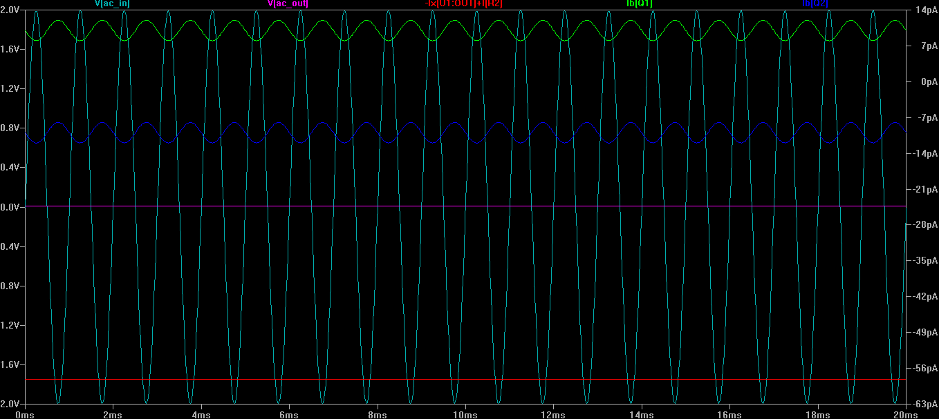
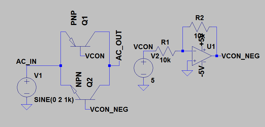
For instance, I drew up and simulated the following BJT schematic. Since it's my own creation, I of course don't trust it, but it seems to work, with only 10nA pulled from the control pin. Could anyone give me a reason why a relay is preferable?
enter image description here

Output is OFF when VCON=5. Current leakage also shown. Output is OFF when VCONT=5. Current leakage also shown. Output is ON when VCON=0 Output is ON when Vcon=0

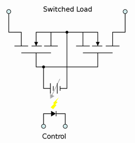
In reference to Russell's comment, I tried to simulate this circuit:

enter image description here

But the control (shown here as voltage source) cannot be grounded. In this pic it works, because the control is isolated. I tried adding a resistor between ground and sources, but that does not allow for full cutoff.

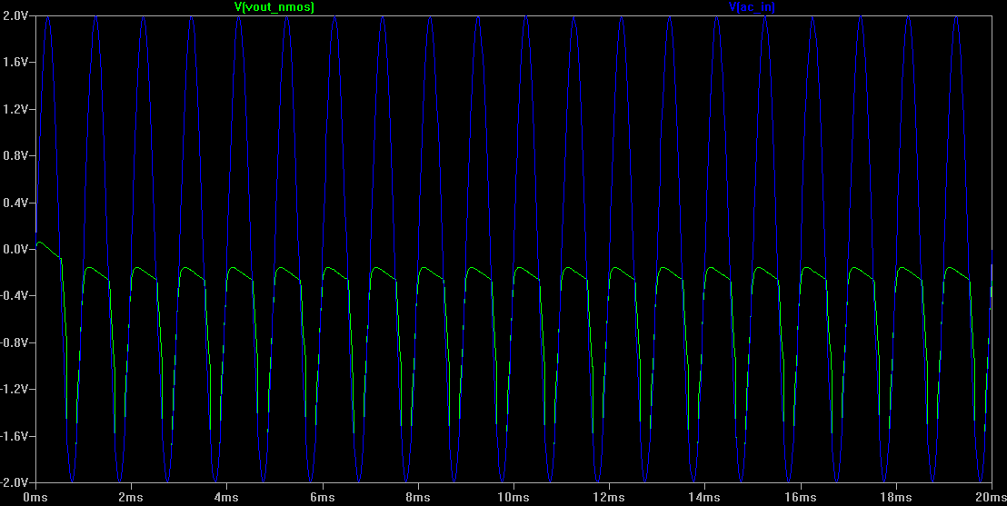
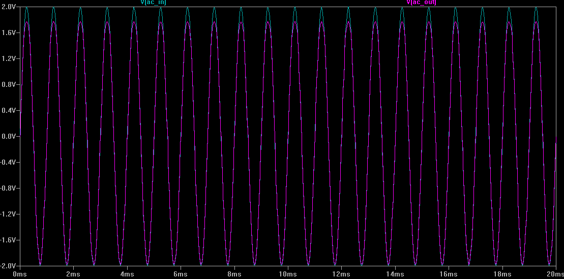
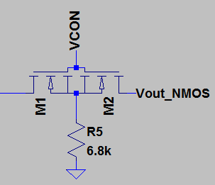
At Russell's behest, I built the NMOS version and it worked even though the simulations show only a dampening for the positive swing:

This was the circuit that was simulated and built/tested: enter image description here

Simulation result: enter image description here

Oscilloscope measurement (when forgetting to ground the Source, or having very high R to ground): enter image description here

Oscilloscope measurement with the 6.8k resistor from S to GND: enter image description here

Voltmeter measurements:

When Vcon=HIGH: 0 uA from Vcon, 12 uA from signal into input, 9 uA from Source to GND.

When Vcon=LOW:0 uA from Vcon, 0 uA from signal to input, 0 uA from Source to GND.

I want to mix up to four AC signals, that may or may not be DC biased, but will always be between -5.6 and +5.6. For that I was going to use a summing amp. (If anyone wants to talk me out of that in a comment, feel free, but that's not the main focus of the question.)

I also want to be able to connect/disconnect the signals to the mixer via a microcontroller. I'm not THAT concerned with a little distortion or delay, since the signals are monotone and mostly for testing purposes. I have read that a relay is probably my best bet, but I don't have any around at the moment. Therefore, I tried to design one using the discrete components I have, which are BJTs, MOSFETs, and the normal passives. I read this post, but I'm not really sure how to apply SCRs or TRIACs. The TRIAC's wiki page lost me when it started talking about quadrants, haha. I just want to pass the signal, or block it.

For instance, I drew up and simulated the following BJT schematic. Since it's my own creation, I of course don't trust it, but it seems to work, with only 10nA pulled from the control pin. Could anyone give me a reason why a relay is preferable?

enter image description here

Output is OFF when VCON=5. Current leakage also shown. Output is OFF when VCONT=5. Current leakage also shown. Output is ON when VCON=0 Output is ON when Vcon=0

In reference to Russell's comment, I tried to simulate this circuit:

enter image description here

But the control (shown here as voltage source) cannot be grounded. In this pic it works, because the control is isolated. I tried adding a resistor between ground and sources, but that does not allow for full cutoff.

At Russell's behest, I built the NMOS version and it worked even though the simulations show only a dampening for the positive swing:

This was the circuit that was simulated and built/tested: enter image description here

Simulation result: enter image description here

Oscilloscope measurement (when forgetting to ground the Source, or having very high R to ground): enter image description here

Oscilloscope measurement with the 6.8k resistor from S to GND: enter image description here

Voltmeter measurements:

When Vcon=HIGH: 0 uA from Vcon, 12 uA from signal into input, 9 uA from Source to GND.

When Vcon=LOW:0 uA from Vcon, 0 uA from signal to input, 0 uA from Source to GND.

added 7 characters in body
Source Link
MrUser
  • 259
  • 1
  • 3
  • 11

I want to mix up to four AC signals, that may or may not be DC biased, but will always be between -5.6 and +5.6. For that I was going to use a summing amp. (If anyone wants to talk me out of that in a comment, feel free, but that's not the main focus of the question.)

I also want to be able to connect/disconnect the signals to the mixer via a microcontroller. I'm not THAT concerned with a little distortion or delay, since the signals are monotone and mostly for testing purposes. I have read that a relay is probably my best bet, but I don't have any around at the moment. Therefore, I tried to design one using the discrete components I have, which are BJTs, MOSFETs, and the normal passives. I read this post, but I'm not really sure how to apply SCRs or TRIACs. The TRIAC's wiki page lost me when it started talking about quadrants, haha. I just want to pass the signal, or block it.

For instance, I drew up and simulated the following BJT schematic. Since it's my own creation, I of course don't trust it, but it seems to work, with only 10nA pulled from the control pin. Could anyone give me a reason why a relay is preferable?

enter image description here

Output is OFF when VCONT=5. Current leakage also shown.Output is OFF when VCON=5. Current leakage also shown. Output is OFF when VCONT=5. Current leakage also shown. Output is ON when VCONT=0Output is ON when VCON=0 Output is ON when VCONT=0Vcon=0

In reference to Russell's comment, I tried to simulate this circuit:

enter image description here

But the control (shown here as voltage source) cannot be grounded. In this pic it works, because the control is isolated. I tried adding a resistor between ground and sources, but that does not allow for full cutoff.

At Russell's behest, I built the NMOS version and it worked even though the simulations show only a dampening for the positive swing:

This was the circuit that was simulated and built/tested: enter image description here

Simulation result: enter image description here

Oscilloscope measurement (when forgetting to ground the Source, or having very high R to ground): enter image description here

Oscilloscope measurement with the 6.8k resistor from S to GND: enter image description here

Voltmeter measurements:

When ONVcon=HIGH: 0 uA from VcontVcon, 12 uA from signal into input, 9 uA from Source to GND.

When OFFVcon=LOW:0 uA from VcontVcon, 0 uA from signal to input, 0 uA from Source to GND.

I want to mix up to four AC signals, that may or may not be DC biased, but will always be between -5.6 and +5.6. For that I was going to use a summing amp. (If anyone wants to talk me out of that in a comment, feel free, but that's not the main focus of the question.)

I also want to be able to connect/disconnect the signals to the mixer via a microcontroller. I'm not THAT concerned with a little distortion or delay, since the signals are monotone and mostly for testing purposes. I have read that a relay is probably my best bet, but I don't have any around at the moment. Therefore, I tried to design one using the discrete components I have, which are BJTs, MOSFETs, and the normal passives. I read this post, but I'm not really sure how to apply SCRs or TRIACs. The TRIAC's wiki page lost me when it started talking about quadrants, haha. I just want to pass the signal, or block it.

For instance, I drew up and simulated the following BJT schematic. Since it's my own creation, I of course don't trust it, but it seems to work, with only 10nA pulled from the control pin. Could anyone give me a reason why a relay is preferable?

enter image description here

Output is OFF when VCONT=5. Current leakage also shown. Output is OFF when VCONT=5. Current leakage also shown. Output is ON when VCONT=0 Output is ON when VCONT=0
In reference to Russell's comment, I tried to simulate this circuit:

enter image description here

But the control (shown here as voltage source) cannot be grounded. In this pic it works, because the control is isolated. I tried adding a resistor between ground and sources, but that does not allow for full cutoff.

At Russell's behest, I built the NMOS version and it worked even though the simulations show only a dampening for the positive swing:

This was the circuit that was simulated and built/tested: enter image description here
Simulation result: enter image description here

Oscilloscope measurement (when forgetting to ground the Source, or having very high R to ground): enter image description here
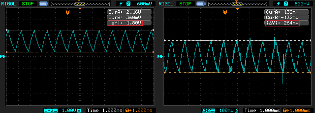
Oscilloscope measurement with the 6.8k resistor from S to GND: enter image description here
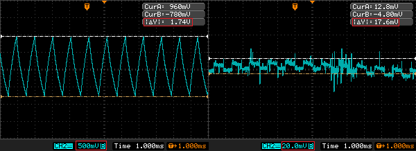
Voltmeter measurements:

When ON: 0 uA from Vcont, 12 uA from signal into input, 9 uA from Source to GND.

When OFF:0 uA from Vcont, 0 uA from signal to input, 0 uA from Source to GND.

I want to mix up to four AC signals, that may or may not be DC biased, but will always be between -5.6 and +5.6. For that I was going to use a summing amp. (If anyone wants to talk me out of that in a comment, feel free, but that's not the main focus of the question.)

I also want to be able to connect/disconnect the signals to the mixer via a microcontroller. I'm not THAT concerned with a little distortion or delay, since the signals are monotone and mostly for testing purposes. I have read that a relay is probably my best bet, but I don't have any around at the moment. Therefore, I tried to design one using the discrete components I have, which are BJTs, MOSFETs, and the normal passives. I read this post, but I'm not really sure how to apply SCRs or TRIACs. The TRIAC's wiki page lost me when it started talking about quadrants, haha. I just want to pass the signal, or block it.

For instance, I drew up and simulated the following BJT schematic. Since it's my own creation, I of course don't trust it, but it seems to work, with only 10nA pulled from the control pin. Could anyone give me a reason why a relay is preferable?

enter image description here

Output is OFF when VCON=5. Current leakage also shown. Output is OFF when VCONT=5. Current leakage also shown. Output is ON when VCON=0 Output is ON when Vcon=0

In reference to Russell's comment, I tried to simulate this circuit:

enter image description here

But the control (shown here as voltage source) cannot be grounded. In this pic it works, because the control is isolated. I tried adding a resistor between ground and sources, but that does not allow for full cutoff.

At Russell's behest, I built the NMOS version and it worked even though the simulations show only a dampening for the positive swing:

This was the circuit that was simulated and built/tested: enter image description here

Simulation result: enter image description here

Oscilloscope measurement (when forgetting to ground the Source, or having very high R to ground): enter image description here

Oscilloscope measurement with the 6.8k resistor from S to GND: enter image description here

Voltmeter measurements:

When Vcon=HIGH: 0 uA from Vcon, 12 uA from signal into input, 9 uA from Source to GND.

When Vcon=LOW:0 uA from Vcon, 0 uA from signal to input, 0 uA from Source to GND.

added 950 characters in body
Source Link
MrUser
  • 259
  • 1
  • 3
  • 11

I want to mix up to four AC signals, that may or may not be DC biased, but will always be between -5.6 and +5.6. For that I was going to use a summing amp. (If anyone wants to talk me out of that in a comment, feel free, but that's not the main focus of the question.)

I also want to be able to connect/disconnect the signals to the mixer via a microcontroller. I'm not THAT concerned with a little distortion or delay, since the signals are monotone and mostly for testing purposes. I have read that a relay is probably my best bet, but I don't have any around at the moment. Therefore, I tried to design one using the discrete components I have, which are BJTs, MOSFETs, and the normal passives. I read this post, but I'm not really sure how to apply SCRs or TRIACs. The TRIAC's wiki page lost me when it started talking about quadrants, haha. I just want to pass the signal, or block it.

For instance, I drew up and simulated the following BJT schematic. Since it's my own creation, I of course don't trust it, but it seems to work, with only 10nA pulled from the control pin. Could anyone give me a reason why a relay is preferable?

enter image description here

Output is OFF when VCONT=5. Current leakage also shown. Output is OFF when VCONT=5. Current leakage also shown. Output is ON when VCONT=0 Output is ON when VCONT=0

In reference to Russell's comment, I tried to simulate this circuit:

enter image description here

But the control (shown here as voltage source) cannot be grounded. In this pic it works, because the control is isolated. I tried adding a resistor between ground and sources, but that does not allow for full cutoff.

At Russell's behest, I built the NMOS version and it worked even though the simulations show only a dampening for the positive swing:

This was the circuit that was simulated and built/tested: enter image description here

Simulation result: enter image description here

Oscilloscope measurement (when forgetting to ground the Source, or having very high R to ground): enter image description here

Oscilloscope measurement with the 6.8k resistor from S to GND: enter image description here

Voltmeter measurements:

When ON: 0 uA from Vcont, 12 uA from signal into input, 9 uA from Source to GND.

When OFF:0 uA from Vcont, 0 uA from signal to input, 0 uA from Source to GND.
I want to mix up to four AC signals, that may or may not be DC biased, but will always be between -5.6 and +5.6. For that I was going to use a summing amp. (If anyone wants to talk me out of that in a comment, feel free, but that's not the main focus of the question.)

I also want to be able to connect/disconnect the signals to the mixer via a microcontroller. I'm not THAT concerned with a little distortion or delay, since the signals are monotone and mostly for testing purposes. I have read that a relay is probably my best bet, but I don't have any around at the moment. Therefore, I tried to design one using the discrete components I have, which are BJTs, MOSFETs, and the normal passives. I read this post, but I'm not really sure how to apply SCRs or TRIACs. The TRIAC's wiki page lost me when it started talking about quadrants, haha. I just want to pass the signal, or block it.

For instance, I drew up and simulated the following BJT schematic. Since it's my own creation, I of course don't trust it, but it seems to work, with only 10nA pulled from the control pin. Could anyone give me a reason why a relay is preferable?

enter image description here

Output is OFF when VCONT=5. Current leakage also shown. Output is OFF when VCONT=5. Current leakage also shown. Output is ON when VCONT=0 Output is ON when VCONT=0

In reference to Russell's comment, I tried to simulate this circuit:

enter image description here

But the control (shown here as voltage source) cannot be grounded. In this pic it works, because the control is isolated. I tried adding a resistor between ground and sources, but that does not allow for full cutoff.

At Russell's behest, I built the NMOS version and it worked even though the simulations show only a dampening for the positive swing:

This was the circuit that was simulated and built/tested: enter image description here

Simulation result: enter image description here

Oscilloscope measurement (when forgetting to ground the Source, or having very high R to ground): enter image description here

Oscilloscope measurement with the 6.8k resistor from S to GND: enter image description here

Voltmeter measurements:

When ON: 0 uA from Vcont, 12 uA from signal into input, 9 uA from Source to GND.

When OFF:0 uA from Vcont, 0 uA from signal to input, 0 uA from Source to GND.
added 378 characters in body
Source Link
MrUser
  • 259
  • 1
  • 3
  • 11
Loading
Added simulation outputs.
Source Link
MrUser
  • 259
  • 1
  • 3
  • 11
Loading
Source Link
MrUser
  • 259
  • 1
  • 3
  • 11
Loading