added 429 characters in body
Source Link
Andy aka
  • 472.9k
  • 29
  • 382
  • 839

Both inputs of the DUT are grounded. There shouldn't be any current flowing through the 10ohm resistor and the 100Kohm resistor, as there is no voltage source.

Wrong - the internal voltage noise source of the inputs is therealways present and that is what is being tested by putting the amplifier into a gain of 10,000.

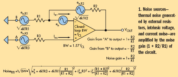
Here is a more general view of op-amp noises: -

enter image description here

The noise source that(implied by the circuit in the question) that is specifically testingbeing tested for is labelled \$e_n\$ in the diagram above.

These number do not exactly match with the description of the circuit (0.1Hz - 10 Hz), but perhaps it's close enough.

They are using two filters at 16.8 Hz which together produce a 3dB point of 10.8 Hz. Having said that this will have a noise bandwidth of 12 to 13Hz (not an exact science) so it's a little too much beyond the 10 Hz limit in my book - this calls into question the guy who designed it.

Both inputs of the DUT are grounded. There shouldn't be any current flowing through the 10ohm resistor and the 100Kohm resistor, as there is no voltage source.

Wrong - the internal voltage noise source of the inputs is there and that is what is being tested by putting the amplifier into a gain of 10,000.

Here is a more general view of op-amp noises: -

enter image description here

The noise source that the circuit in the question is specifically testing for is labelled \$e_n\$ in the diagram above.

Both inputs of the DUT are grounded. There shouldn't be any current flowing through the 10ohm resistor and the 100Kohm resistor, as there is no voltage source.

Wrong - the internal voltage noise source of the inputs is always present and that is what is being tested by putting the amplifier into a gain of 10,000.

Here is a more general view of op-amp noises: -

enter image description here

The noise source (implied by the circuit in the question) that is specifically being tested for is labelled \$e_n\$ in the diagram above.

These number do not exactly match with the description of the circuit (0.1Hz - 10 Hz), but perhaps it's close enough.

They are using two filters at 16.8 Hz which together produce a 3dB point of 10.8 Hz. Having said that this will have a noise bandwidth of 12 to 13Hz (not an exact science) so it's a little too much beyond the 10 Hz limit in my book - this calls into question the guy who designed it.

Source Link
Andy aka
  • 472.9k
  • 29
  • 382
  • 839

Both inputs of the DUT are grounded. There shouldn't be any current flowing through the 10ohm resistor and the 100Kohm resistor, as there is no voltage source.

Wrong - the internal voltage noise source of the inputs is there and that is what is being tested by putting the amplifier into a gain of 10,000.

Here is a more general view of op-amp noises: -

enter image description here

The noise source that the circuit in the question is specifically testing for is labelled \$e_n\$ in the diagram above.