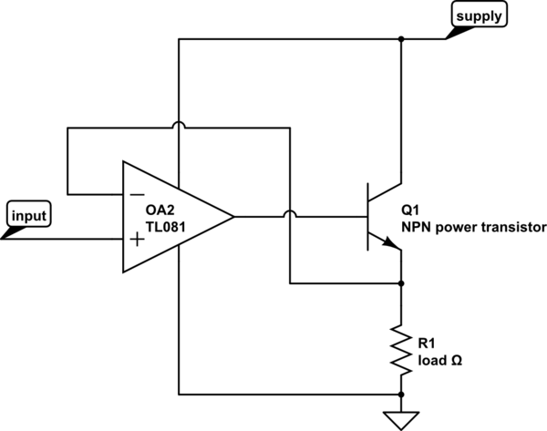
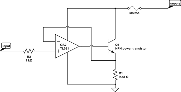
Your schematic shows a "buffer" circuit, the opamp just copies the input voltage at it's + input to the output, provided it can drive the output to this voltage and provided the output is loaded such that it can deliver the current.
If you would not use such a "buffer" circuit, all the current to the load would have to come from the analog PCI card in the PC. These are usually not designed to deliver much current, 10 mA will usually be problematic already. So you need something to fix that, this is called a buffer.
You do not need the 200 ohms R1 resistor, you can connect the - input directly to the output of the opamp.
You say you want to control the current but actually this circuit controls the voltage ! Now if the load is constant, for example 45 ohms then this makes no difference as I = V / R. If this is OK for you, meaning that the load will always be 45 ohms, then this circuit is fine.
BUT 90 mA will be too much for many opamps, however there are some power opamps that can handle this you will have to look at the opamp's datasheet. You can also let the opamp control a small power transistor so that the power transistor does all the hard work. That would look like:


simulate this circuitsimulate this circuit – Schematic created using CircuitLab
