added 205 characters in body
Source Link
user246100
  • 117
  • 1
  • 6

I want to use a N Mosfet for switching a device from a microcontroller (5V current and 5V signal), and a P Mosfet for giving a signal to the same microcontroller (5V signal , 12V input). (Device current draw in the order of few 100s of milliamps.

I'm having trouble in finding the specs that make the components suitable for those specific tasks. I had the following problems.

Problem 1 - With N Mosfet, this layout won't work because there is a big drop in the mosfet, and the load gets something like 2.8V.
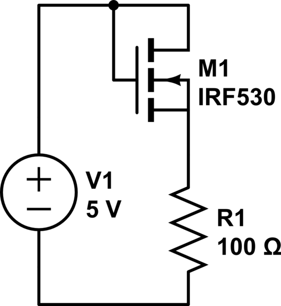
schematic

simulate this circuit – Schematic created using CircuitLab

If I give it instead 12V, there is no longer a big drop, and it works like I intended.

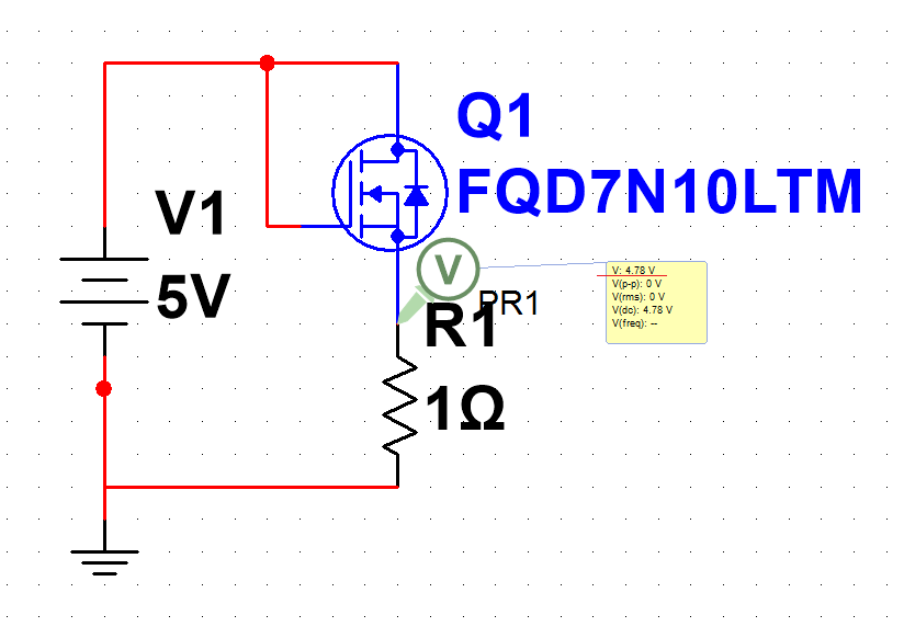
Before I requested this particular component from an online seller, I tested in its simulator (MultiSIM BLUE) and even with a load of 1 Ohm, the voltage out is 4.78V. I don't know if this is acceptable for a simulator or if I should complaint about it.

N Mosfet in Simulator

The particular Mosfet is this one.

http://eu.mouser.com/Search/ProductDetail.aspx?R=FQD7N10LTM

I solved this issue by connecting the load directly to 5V and it's ground to the mosfet and that way it works as I intended.
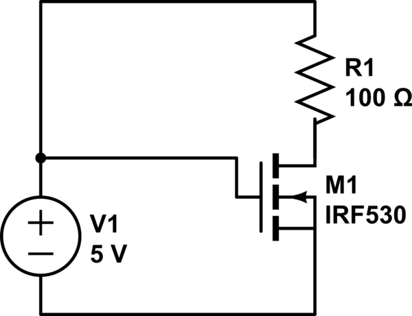
schematic

simulate this circuit

Anyway I would like to ask why does this happen, and how the input voltage makes a difference, and which mosfet I could buy that would solve this problem.

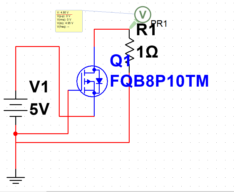
Problem 2 - With the P Mosfet, if I give it 5V in the source and I give it 0V in gate, it won't "open" or at least not fully, so I can't get 5V on the drain. If I use 12V instead it works as intended. Notice that I want to use the P Mosfet giving 12V in the gate to "close it" so it "passes" 5V but I'm not even in that phase, since I can't even make it work with 0V.

As for the N Mosfet, I tested the behaviour in simulator, and it worked as I intended.

enter image description here

This is the particular mosfet:

http://eu.mouser.com/Search/ProductDetail.aspx?R=FQB8P10TM

Now, if I do the same thing as I did for the N Mosfet, and change the load position in the circuit, the mosfet now conducts, but I only get 1.1V. If I connect it to 12V, I get 7.70V.

So, basically, I want to work with Mosfets as logic gates but they just won't work with 5V as I intended. My two final questions are:

How do I choose the two Mosfets for this tasks? I the behaviour of the simulator? Why the N Mosfet works ok I the other configuration? If I complain to Mouser, will/should they give me replacements?

Notice that I'm talking about "Logic" but I think that I don't even have to use Logic Level Mosfets because I'm switching with the same voltage level for gate and input. Anyway, the N Mosfet is Logic Level.

So, one more questions: is there a need of Logic Level Mosfet for some of these situations?

Post note: I talk throughout the text about using 12V for testing, it's just because that value is one that I happen to have around, and I noticed that it makes a difference for both of these mosfets.

I want to use a N Mosfet for switching a device from a microcontroller (5V current and 5V signal), and a P Mosfet for giving a signal to the same microcontroller (5V signal , 12V input). (Device current draw in the order of few 100s of milliamps.

I'm having trouble in finding the specs that make the components suitable for those specific tasks. I had the following problems.

Problem 1 - With N Mosfet, this layout won't work because there is a big drop in the mosfet, and the load gets something like 2.8V.

schematic

simulate this circuit – Schematic created using CircuitLab

If I give it instead 12V, there is no longer a big drop, and it works like I intended.

Before I requested this particular component from an online seller, I tested in its simulator (MultiSIM BLUE) and even with a load of 1 Ohm, the voltage out is 4.78V. I don't know if this is acceptable for a simulator or if I should complaint about it.

N Mosfet in Simulator

The particular Mosfet is this one.

http://eu.mouser.com/Search/ProductDetail.aspx?R=FQD7N10LTM

I solved this issue by connecting the load directly to 5V and it's ground to the mosfet and that way it works as I intended.

schematic

simulate this circuit

Anyway I would like to ask why does this happen, and how the input voltage makes a difference, and which mosfet I could buy that would solve this problem.

Problem 2 - With the P Mosfet, if I give it 5V in the source and I give it 0V in gate, it won't "open" or at least not fully, so I can't get 5V on the drain. If I use 12V instead it works as intended. Notice that I want to use the P Mosfet giving 12V in the gate to "close it" so it "passes" 5V but I'm not even in that phase, since I can't even make it work with 0V.

As for the N Mosfet, I tested the behaviour in simulator, and it worked as I intended.

enter image description here

This is the particular mosfet:

http://eu.mouser.com/Search/ProductDetail.aspx?R=FQB8P10TM

Now, if I do the same thing as I did for the N Mosfet, and change the load position in the circuit, the mosfet now conducts, but I only get 1.1V. If I connect it to 12V, I get 7.70V.

So, basically, I want to work with Mosfets as logic gates but they just won't work with 5V as I intended. My two final questions are:

How do I choose the two Mosfets for this tasks? I the behaviour of the simulator? Why the N Mosfet works ok I the other configuration? If I complain to Mouser, will/should they give me replacements?

Notice that I'm talking about "Logic" but I think that I don't even have to use Logic Level Mosfets because I'm switching with the same voltage level for gate and input. Anyway, the N Mosfet is Logic Level.

So, one more questions: is there a need of Logic Level Mosfet for some of these situations?

Post note: I talk throughout the text about using 12V for testing, it's just because that value is one that I happen to have around, and I noticed that it makes a difference for both of these mosfets.
Source Link
user246100
  • 117
  • 1
  • 6

Mosfets characteristics suitable for 5V

I want to use a N Mosfet for switching a device from a microcontroller (5V current and 5V signal), and a P Mosfet for giving a signal to the same microcontroller (5V signal , 12V input). (Device current draw in the order of few 100s of milliamps.

I'm having trouble in finding the specs that make the components suitable for those specific tasks. I had the following problems.

Problem 1 - With N Mosfet, this layout won't work because there is a big drop in the mosfet, and the load gets something like 2.8V.

schematic

simulate this circuit – Schematic created using CircuitLab

If I give it instead 12V, there is no longer a big drop, and it works like I intended.

Before I requested this particular component from an online seller, I tested in its simulator (MultiSIM BLUE) and even with a load of 1 Ohm, the voltage out is 4.78V. I don't know if this is acceptable for a simulator or if I should complaint about it.

N Mosfet in Simulator

The particular Mosfet is this one.

http://eu.mouser.com/Search/ProductDetail.aspx?R=FQD7N10LTM

I solved this issue by connecting the load directly to 5V and it's ground to the mosfet and that way it works as I intended.

schematic

simulate this circuit

Anyway I would like to ask why does this happen, and how the input voltage makes a difference, and which mosfet I could buy that would solve this problem.

Problem 2 - With the P Mosfet, if I give it 5V in the source and I give it 0V in gate, it won't "open" or at least not fully, so I can't get 5V on the drain. If I use 12V instead it works as intended. Notice that I want to use the P Mosfet giving 12V in the gate to "close it" so it "passes" 5V but I'm not even in that phase, since I can't even make it work with 0V.

As for the N Mosfet, I tested the behaviour in simulator, and it worked as I intended.

enter image description here

This is the particular mosfet:

http://eu.mouser.com/Search/ProductDetail.aspx?R=FQB8P10TM

Now, if I do the same thing as I did for the N Mosfet, and change the load position in the circuit, the mosfet now conducts, but I only get 1.1V. If I connect it to 12V, I get 7.70V.

So, basically, I want to work with Mosfets as logic gates but they just won't work with 5V as I intended. My two final questions are:

How do I choose the two Mosfets for this tasks? I the behaviour of the simulator? Why the N Mosfet works ok I the other configuration? If I complain to Mouser, will/should they give me replacements?

Notice that I'm talking about "Logic" but I think that I don't even have to use Logic Level Mosfets because I'm switching with the same voltage level for gate and input. Anyway, the N Mosfet is Logic Level.

So, one more questions: is there a need of Logic Level Mosfet for some of these situations?