Mod Moved Comments To Chat
deleted 27 characters in body
Source Link
John M.
  • 903
  • 1
  • 14
  • 25

With the MMA8452, it claims that it draws 44uA when ODR = 100Hz and 24uA when ODR = 6.25Hz in Normal Mode.

However, I'm measuring 1.5mA when ODR = 100Hz. Does anyone know how this could be the case? In Low Power Mode, I'm getting almost identical values. I get even higher values in High Resolution mode.

I'm using a 100R shunt and I'm getting the same values with a scope and with a DMM. I'm using a GY-45, but the I2C pull-ups wouldn't draw that much more current - right?

Any help will be appreciated.

UPDATE 1:

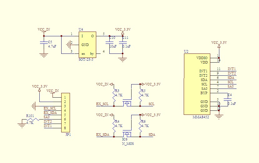
Here's the circuit for GY-45

enter image description here

I'm tried powering it by using the VCC_IN power line with 3.3V and VCC_3.3V with 3.3V. Same measurements.

I did some more measurements. The Vds across the NFETs are around 0.12V. The voltage across the two left 4.7K are around 0.08V and the voltage across the two right 4.7K are around 0.02V. Do these figure help an explanation?

UPDATE 2:

I've desoldered the LDO and have supplied 3.3V and 5V to Vin, but same measurements.
With the MMA8452, it claims that it draws 44uA when ODR = 100Hz in Normal Mode.

However, I'm measuring 1.5mA when ODR = 100Hz. Does anyone know how this could be the case? In Low Power Mode, I'm getting almost identical values. I get even higher values in High Resolution mode.

I'm using a 100R shunt and I'm getting the same values with a scope and with a DMM. I'm using a GY-45, but the I2C pull-ups wouldn't draw that much more current - right?

Any help will be appreciated.

UPDATE 1:

Here's the circuit for GY-45

enter image description here

I'm tried powering it by using the VCC_IN power line with 3.3V and VCC_3.3V with 3.3V. Same measurements.

I did some more measurements. The Vds across the NFETs are around 0.12V. The voltage across the two left 4.7K are around 0.08V and the voltage across the two right 4.7K are around 0.02V. Do these figure help an explanation?

UPDATE 2:

I've desoldered the LDO and have supplied 3.3V and 5V to Vin, but same measurements.

deleted 101 characters in body
Source Link
John M.
  • 903
  • 1
  • 14
  • 25

With the MMA8452, it claims that it draws 44uA when ODR = 100Hz and 24uA when ODR = 6.25Hz in Normal Mode.

However, I'm measuring 1.5mA when ODR = 100Hz and 2.2mA when ODR = 6.25Hz in Normal Mode. Does anyone know how this could be the case? In particular, 6.25Hz draws more current than 100Hz does! In Low Power Mode, I'm getting almost identical values. I get even higher values in High Resolution mode.

I'm using a 100R shunt and I'm getting the same values with a scope and with a DMM. I'm using a GY-45, but the I2C pull-ups wouldn't draw that much more current - right?

Any help will be appreciated.

UPDATE 1:

Here's the circuit for GY-45

enter image description here

I'm tried powering it by using the VCC_IN power line with 3.3V and VCC_3.3V with 3.3V. Same measurements.

I did some more measurements. The Vds across the NFETs are around 0.12V. The voltage across the two left 4.7K are around 0.08V and the voltage across the two right 4.7K are around 0.02V. Do these figure help an explanation?

UPDATE 2:

I've desoldered the LDO and have supplied 3.3V and 5V to Vin, but same measurements.

With the MMA8452, it claims that it draws 44uA when ODR = 100Hz and 24uA when ODR = 6.25Hz in Normal Mode.

However, I'm measuring 1.5mA when ODR = 100Hz and 2.2mA when ODR = 6.25Hz in Normal Mode. Does anyone know how this could be the case? In particular, 6.25Hz draws more current than 100Hz does! In Low Power Mode, I'm getting almost identical values. I get even higher values in High Resolution mode.

I'm using a 100R shunt and I'm getting the same values with a scope and with a DMM. I'm using a GY-45, but the I2C pull-ups wouldn't draw that much more current - right?

Any help will be appreciated.

UPDATE:

Here's the circuit for GY-45

enter image description here

I'm tried powering it by using the VCC_IN power line with 3.3V and VCC_3.3V with 3.3V. Same measurements.

I did some more measurements. The Vds across the NFETs are around 0.12V. The voltage across the two left 4.7K are around 0.08V and the voltage across the two right 4.7K are around 0.02V. Do these figure help an explanation?

With the MMA8452, it claims that it draws 44uA when ODR = 100Hz and 24uA when ODR = 6.25Hz in Normal Mode.

However, I'm measuring 1.5mA when ODR = 100Hz. Does anyone know how this could be the case? In Low Power Mode, I'm getting almost identical values. I get even higher values in High Resolution mode.

I'm using a 100R shunt and I'm getting the same values with a scope and with a DMM. I'm using a GY-45, but the I2C pull-ups wouldn't draw that much more current - right?

Any help will be appreciated.

UPDATE 1:

Here's the circuit for GY-45

enter image description here

I'm tried powering it by using the VCC_IN power line with 3.3V and VCC_3.3V with 3.3V. Same measurements.

I did some more measurements. The Vds across the NFETs are around 0.12V. The voltage across the two left 4.7K are around 0.08V and the voltage across the two right 4.7K are around 0.02V. Do these figure help an explanation?

UPDATE 2:

I've desoldered the LDO and have supplied 3.3V and 5V to Vin, but same measurements.

added 227 characters in body
Source Link
John M.
  • 903
  • 1
  • 14
  • 25

With the MMA8452, it claims that it draws 44uA when ODR = 100Hz and 24uA when ODR = 6.25Hz in Normal Mode.

However, I'm measuring 1.5mA when ODR = 100Hz and 2.2mA when ODR = 6.25Hz in Normal Mode. Does anyone know how this could be the case? In particular, 6.25Hz draws more current than 100Hz does! In Low Power Mode, I'm getting almost identical values. I get even higher values in High Resolution mode.

I'm using a 100R shunt and I'm getting the same values with a scope and with a DMM. I'm using a GY-45, but the I2C pull-ups wouldn't draw that much more current - right?

Any help will be appreciated.

UPDATE:

Here's the circuit for GY-45

enter image description here

I'm tried powering it by using the VCC_IN power line with 3.3V and VCC_3.3V with 3.3V. Same measurements.

I did some more measurements. The Vds across the NFETs are around 0.12V. The voltage across the two left 4.7K are around 0.08V and the voltage across the two right 4.7K are around 0.02V. Do these figure help an explanation?

With the MMA8452, it claims that it draws 44uA when ODR = 100Hz and 24uA when ODR = 6.25Hz in Normal Mode.

However, I'm measuring 1.5mA when ODR = 100Hz and 2.2mA when ODR = 6.25Hz in Normal Mode. Does anyone know how this could be the case? In particular, 6.25Hz draws more current than 100Hz does! In Low Power Mode, I'm getting almost identical values. I get even higher values in High Resolution mode.

I'm using a 100R shunt and I'm getting the same values with a scope and with a DMM. I'm using a GY-45, but the I2C pull-ups wouldn't draw that much more current - right?

Any help will be appreciated.

UPDATE:

Here's the circuit for GY-45

enter image description here

I'm tried powering it by using the VCC_IN power line with 3.3V and VCC_3.3V with 3.3V. Same measurements.

I did some more measurements. The Vds across the NFETs are around 0.12V. The voltage across the two left 4.7K are around 0.08V and the voltage across the two right 4.7K are around 0.02V. Do these figure help an explanation?

Tweeted twitter.com/#!/StackElectronix/status/648750329111158785
added 65 characters in body
Source Link
John M.
  • 903
  • 1
  • 14
  • 25
Loading
added 130 characters in body
Source Link
John M.
  • 903
  • 1
  • 14
  • 25
Loading
Source Link
John M.
  • 903
  • 1
  • 14
  • 25
Loading