Commonmark migration
Source Link
  • Fig 1 shows max current with frequency. It's happy enough at 1 kHz, getting unhappy at 10 kHz and getting bad much above that. 1 kHz is quite slow PWM, but ore than fast enough to avoid lamp flicker.

  • Fig 5 shows that you will get under 2V drop at 1Amp - maybe 1V drop.

    At 1A x 2V you get ~2 Watt dissipation plus there are switching losses.

At 1A x 2V you get ~2 Watt dissipation plus there are switching losses.

  • fig 10 shows that switching losses are small at 1 kHz compared to energy loss due to the 1V to 2V turned on voltage at 1A.

    fig 10 shows that switching losses are small at 1 kHz compared to energy loss due to the 1V to 2V turned on voltage at 1A.

  • 600V, 8A.

  • Up to +/- 30V AC drive on gate so more rugged than most.

  • The "FullPAK" TO220 type case is fully insulated, making it safer to use.

  • It will run OK at 5V drive with <= 2A load - much happier at say 6V or more drive.

  • Rdson = on resistance is slightly over 1 ohm at up to several amps load at 5V drive. So say 1.5W losses at 1A and 3W at 2A. (Page 10, various figs).

    A similar heatsink to that for the IGBT is required.
    For say 30C temperature rise at 3 at a 30/3 = 10 C/W heatsink is needed.
    The FullPAk pkg adds another 4.3C/W thermal resistance.

A similar heatsink to that for the IGBT is required.
For say 30C temperature rise at 3 at a 30/3 = 10 C/W heatsink is needed.
The FullPAk pkg adds another 4.3C/W thermal resistance.

  • BUT switching times of well under 100 nanoseconds mean it is suited to far higher PWM frequencies than the IGBT.

    BUT switching times of well under 100 nanoseconds mean it is suited to far higher PWM frequencies than the IGBT.

  • Fig 1 shows max current with frequency. It's happy enough at 1 kHz, getting unhappy at 10 kHz and getting bad much above that. 1 kHz is quite slow PWM, but ore than fast enough to avoid lamp flicker.

  • Fig 5 shows that you will get under 2V drop at 1Amp - maybe 1V drop.

At 1A x 2V you get ~2 Watt dissipation plus there are switching losses.

  • fig 10 shows that switching losses are small at 1 kHz compared to energy loss due to the 1V to 2V turned on voltage at 1A.
  • 600V, 8A.

  • Up to +/- 30V AC drive on gate so more rugged than most.

  • The "FullPAK" TO220 type case is fully insulated, making it safer to use.

  • It will run OK at 5V drive with <= 2A load - much happier at say 6V or more drive.

  • Rdson = on resistance is slightly over 1 ohm at up to several amps load at 5V drive. So say 1.5W losses at 1A and 3W at 2A. (Page 10, various figs).

A similar heatsink to that for the IGBT is required.
For say 30C temperature rise at 3 at a 30/3 = 10 C/W heatsink is needed.
The FullPAk pkg adds another 4.3C/W thermal resistance.

  • BUT switching times of well under 100 nanoseconds mean it is suited to far higher PWM frequencies than the IGBT.
  • Fig 1 shows max current with frequency. It's happy enough at 1 kHz, getting unhappy at 10 kHz and getting bad much above that. 1 kHz is quite slow PWM, but ore than fast enough to avoid lamp flicker.

  • Fig 5 shows that you will get under 2V drop at 1Amp - maybe 1V drop.

    At 1A x 2V you get ~2 Watt dissipation plus there are switching losses.

  • fig 10 shows that switching losses are small at 1 kHz compared to energy loss due to the 1V to 2V turned on voltage at 1A.

  • 600V, 8A.

  • Up to +/- 30V AC drive on gate so more rugged than most.

  • The "FullPAK" TO220 type case is fully insulated, making it safer to use.

  • It will run OK at 5V drive with <= 2A load - much happier at say 6V or more drive.

  • Rdson = on resistance is slightly over 1 ohm at up to several amps load at 5V drive. So say 1.5W losses at 1A and 3W at 2A. (Page 10, various figs).

    A similar heatsink to that for the IGBT is required.
    For say 30C temperature rise at 3 at a 30/3 = 10 C/W heatsink is needed.
    The FullPAk pkg adds another 4.3C/W thermal resistance.

  • BUT switching times of well under 100 nanoseconds mean it is suited to far higher PWM frequencies than the IGBT.

Source Link
Russell McMahon
  • 152.1k
  • 18
  • 218
  • 403

Where did you get your IGBT model from?
Is it a model for the actual part of a generic IGBT model?
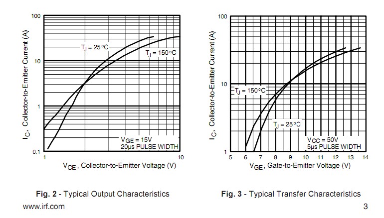
The part that you have chosen should typically work with 5V drive but the curves in fig 3 below show that you typically need at least 6.5V drive and that say 8V+ drive would be better. Notice that the maximum gate drive voltage shown on the graph is 13.5V even though the device is 20V gate voltage rated. Operation well below rated gate voltage is a good safety aim as long as the device works well at the chosen gate voltage

The IRG4BC10U IGBT datasheet can be found here

This is a nice part that is well suited to your need IF PWM frequency is not too high and as long as you provide enough gate drive.

Data sheet page 2 says VGE(th) = gate threshold = minimum turn of voltage is 6V max (worst case) so you MUST use at least 6V drive in a prope design.

Data sheet fig 3 page 3 shows you can get 10A at 9V drive - which should be ample for you. 10A x 110 ~= 1 kiloWatt!. For other reasons you would have trouble reaching that current but you don't need to. A 100 Watt lamp requires about 1 Amp at 100 VAC once warmed up.

enter image description here

HOWEVER

  • Fig 1 shows max current with frequency. It's happy enough at 1 kHz, getting unhappy at 10 kHz and getting bad much above that. 1 kHz is quite slow PWM, but ore than fast enough to avoid lamp flicker.

  • Fig 5 shows that you will get under 2V drop at 1Amp - maybe 1V drop.

At 1A x 2V you get ~2 Watt dissipation plus there are switching losses.

  • fig 10 shows that switching losses are small at 1 kHz compared to energy loss due to the 1V to 2V turned on voltage at 1A.

So, overall - with about 10V gate drive and 1 kHz PWM and a modest heatsink this IGBT will work OK at 110 VAC, 1A.

BUT a MOSFET may be a better choice - higher PWM without the losses of the IGBT.

The Infineon IPA60R520E6 MOSFET is in stock at Digikey at about $2/1 Datasheet here.

  • 600V, 8A.

  • Up to +/- 30V AC drive on gate so more rugged than most.

  • The "FullPAK" TO220 type case is fully insulated, making it safer to use.

  • It will run OK at 5V drive with <= 2A load - much happier at say 6V or more drive.

  • Rdson = on resistance is slightly over 1 ohm at up to several amps load at 5V drive. So say 1.5W losses at 1A and 3W at 2A. (Page 10, various figs).

A similar heatsink to that for the IGBT is required.
For say 30C temperature rise at 3 at a 30/3 = 10 C/W heatsink is needed.
The FullPAk pkg adds another 4.3C/W thermal resistance.

  • BUT switching times of well under 100 nanoseconds mean it is suited to far higher PWM frequencies than the IGBT.

Overall, the FET would work well and allow wider choice of PWM frequencies.