added 158 characters in body
Source Link

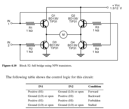
If you want to make an all-NPN H-bridge, the schematic and associated logic is as follows:

enter image description here

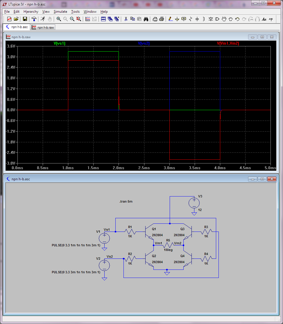
Do not use these power transistors straight from a uC though. You will not be able to saturate them and they will likely burn. Lower power transistors will work though, beta in saturation is about 10. Also this circuit doesn't show any flyback diodes, so it's just conceptual. Furthermore, with an NPN H-bridge, you cannot exceed (at the motor) the voltage of your driving signal (so at most +/-3.3V); note that this happens even if I use a much larger value for the H-bridge's own supply (like 12V):

enter image description here

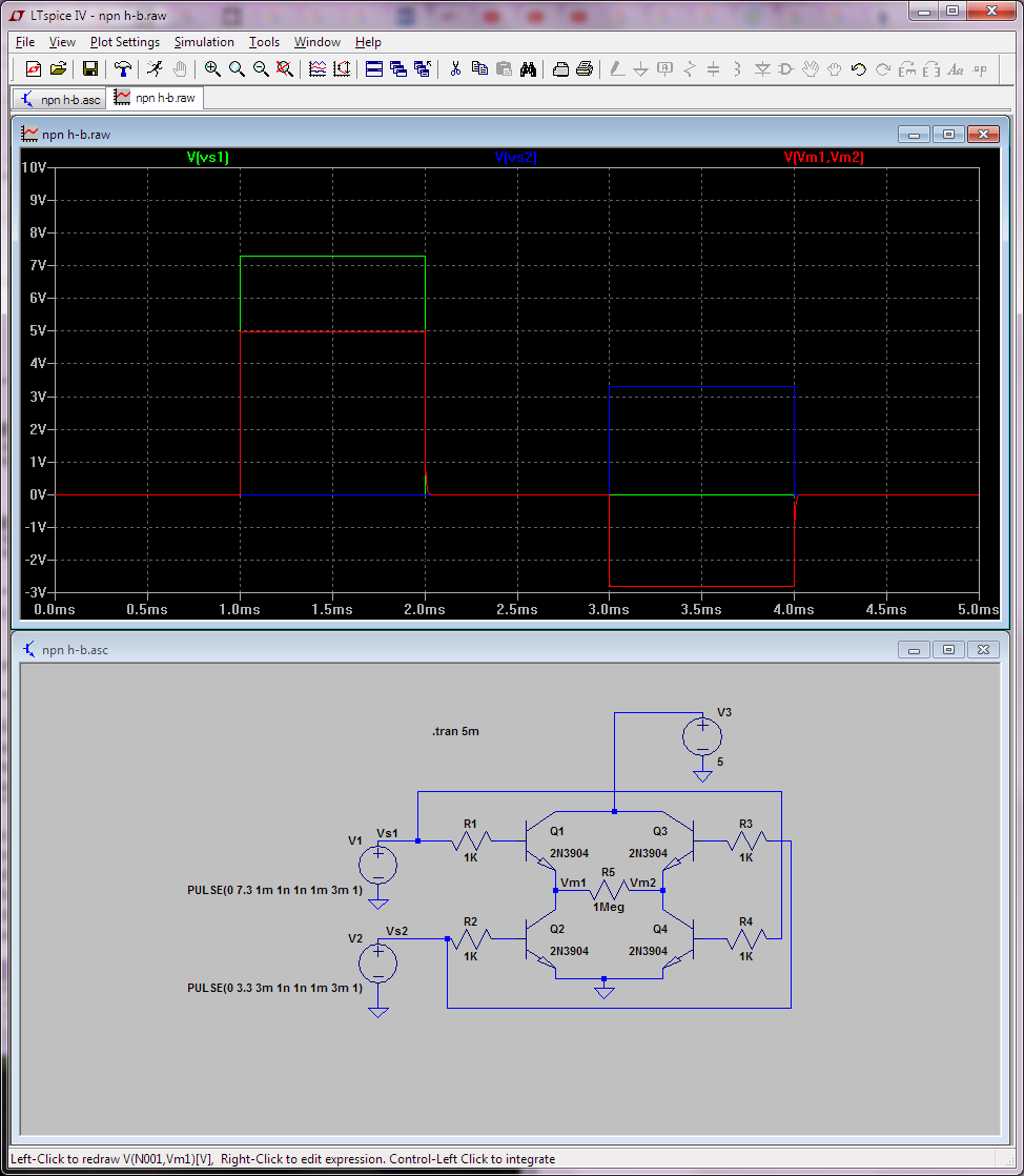
To actually get 5V at the motor, your signal needs to drive the transistor's bases above Vcc, like below for example where I've changed the first signal to 7.3V:

enter image description here

That's why all-NPN H-bridges aren't so popular.

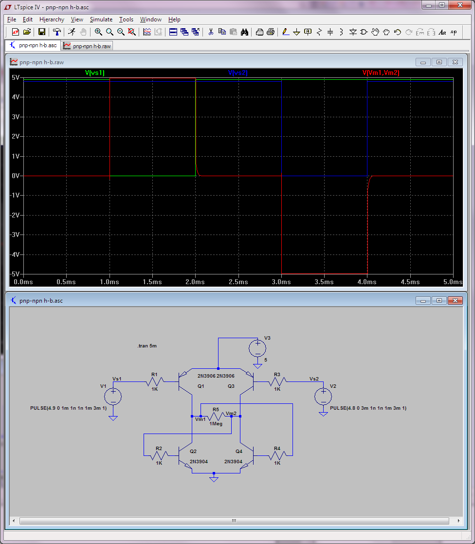
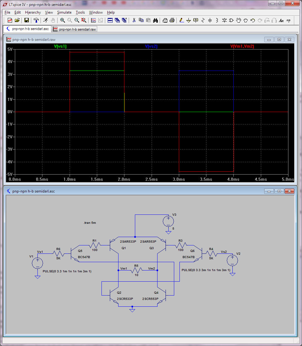
So in case you wonder what's the advantage of PNPs on the high-side... First let's see what would look like...

enter image description here

Note that the input signals are now active low... and you need to keep them at (5v) rails on "off". I've fuzzed their values a little bit (4.8 and 4.9V) so you so you can see them clearly on the graph. Doesn't look like much of an advantage just like this, that's why you normally see another transistor in front of them (to inverse the logic and do logic level translation) as shown below:

enter image description here

Now you can drive this with 3.3V logic and get 5V at the motor. Also note that this circuit needs a proper (low resistance) load to actually work. MOSFETs class next week... Actually you can look at these lab notes for the MOSFET equivalent of this latter circuit.

And in case it wasn't obvious, the easiest thing is to use an H-bridge made by somebody else, like an integrated circuit H-bridge of which there are many you can buy.

If you want to make an all-NPN H-bridge, the schematic and associated logic is as follows:

enter image description here

Do not use these power transistors straight from a uC though. You will not be able to saturate them and they will likely burn. Lower power transistors will work though, beta in saturation is about 10. Also this circuit doesn't show any flyback diodes, so it's just conceptual. Furthermore, with an NPN H-bridge, you cannot exceed (at the motor) the voltage of your driving signal (so at most +/-3.3V); note that this happens even if I use a much larger value for the H-bridge's own supply (like 12V):

enter image description here

To actually get 5V at the motor, your signal needs to drive the transistor's bases above Vcc, like below for example where I've changed the first signal to 7.3V:

enter image description here

That's why all-NPN H-bridges aren't so popular.

So in case you wonder what's the advantage of PNPs on the high-side... First let's see what would look like...

enter image description here

Note that the input signals are now active low... and you need to keep them at (5v) rails on "off". I've fuzzed their values a little bit (4.8 and 4.9V) so you so you can see them clearly on the graph. Doesn't look like much of an advantage just like this, that's why you normally see another transistor in front of them (to inverse the logic and do logic level translation) as shown below:

enter image description here

Now you can drive this with 3.3V logic and get 5V at the motor. Also note that this circuit needs a proper (low resistance) load to actually work. MOSFETs class next week...

And in case it wasn't obvious, the easiest thing is to use an H-bridge made by somebody else, like an integrated circuit H-bridge of which there are many you can buy.
If you want to make an all-NPN H-bridge, the schematic and associated logic is as follows:

enter image description here

Do not use these power transistors straight from a uC though. You will not be able to saturate them and they will likely burn. Lower power transistors will work though, beta in saturation is about 10. Also this circuit doesn't show any flyback diodes, so it's just conceptual. Furthermore, with an NPN H-bridge, you cannot exceed (at the motor) the voltage of your driving signal (so at most +/-3.3V); note that this happens even if I use a much larger value for the H-bridge's own supply (like 12V):

enter image description here

To actually get 5V at the motor, your signal needs to drive the transistor's bases above Vcc, like below for example where I've changed the first signal to 7.3V:

enter image description here

That's why all-NPN H-bridges aren't so popular.

So in case you wonder what's the advantage of PNPs on the high-side... First let's see what would look like...

enter image description here

Note that the input signals are now active low... and you need to keep them at (5v) rails on "off". I've fuzzed their values a little bit (4.8 and 4.9V) so you so you can see them clearly on the graph. Doesn't look like much of an advantage just like this, that's why you normally see another transistor in front of them (to inverse the logic and do logic level translation) as shown below:

enter image description here

Now you can drive this with 3.3V logic and get 5V at the motor. Also note that this circuit needs a proper (low resistance) load to actually work. MOSFETs class next week... Actually you can look at these lab notes for the MOSFET equivalent of this latter circuit.

And in case it wasn't obvious, the easiest thing is to use an H-bridge made by somebody else, like an integrated circuit H-bridge of which there are many you can buy.
added 858 characters in body
Source Link

If you want to make an all-NPN H-bridge, the schematic and associated logic is as follows:

enter image description here

Do not use these power transistors straight from a uC though. You will not be able to saturate them and they will likely burn. Lower power transistors will work though, beta in saturation is about 10. Also this circuit doesn't show any flyback diodes, so it's just conceptual. Furthermore, with an NPN H-bridge, you cannot exceed (at the motor) the voltage of your driving signal (so at most +/-3.3V); note that this happens even if I use a much larger value for the H-bridge's own supply (like 12V):

enter image description here

To actually get 5V at the motor, your signal needs to drive the transistor's bases above Vcc, like below for example where I've changed the first signal to 7.3V:

enter image description here

That's why all-NPN H-bridges aren't so popular.

So in case you wonder what's the advantage of PNPs on the high-side... First let's see what would look like...

enter image description here

Note that the input signals are now active low... and you need to keep them at (5v) rails on "off". I've fuzzed their values a little bit (4.8 and 4.9V) so you so you can see them clearly on the graph. Doesn't look like much of an advantage just like this, that's why you normally see another transistor in front of them (to inverse the logic and do logic level translation) as shown below:

enter image description here

Now you can drive this with 3.3V logic and get 5V at the motor. Also note that this circuit needs a proper (low resistance) load to actually work. MOSFETs class next week...

And in case it wasn't obvious, the easiest thing is to use an H-bridge made by somebody else, like an integrated circuit H-bridge of which there are many you can buy.
If you want to make an all-NPN H-bridge, the schematic and associated logic is as follows:

enter image description here

Do not use these power transistors straight from a uC though. You will not be able to saturate them and they will likely burn. Lower power transistors will work though, beta in saturation is about 10. Also this circuit doesn't show any flyback diodes, so it's just conceptual. Furthermore, with an NPN H-bridge, you cannot exceed (at the motor) the voltage of your driving signal (so at most +/-3.3V); note that this happens even if I use a much larger value for the H-bridge's own supply (like 12V):

enter image description here

To actually get 5V at the motor, your signal needs to drive the transistor's bases above Vcc, like below for example where I've changed the first signal to 7.3V:

enter image description here

That's why all-NPN H-bridges aren't so popular.

And in case it wasn't obvious, the easiest thing is to use an H-bridge made by somebody else, like an integrated circuit H-bridge of which there are many you can buy.
If you want to make an all-NPN H-bridge, the schematic and associated logic is as follows:

enter image description here

Do not use these power transistors straight from a uC though. You will not be able to saturate them and they will likely burn. Lower power transistors will work though, beta in saturation is about 10. Also this circuit doesn't show any flyback diodes, so it's just conceptual. Furthermore, with an NPN H-bridge, you cannot exceed (at the motor) the voltage of your driving signal (so at most +/-3.3V); note that this happens even if I use a much larger value for the H-bridge's own supply (like 12V):

enter image description here

To actually get 5V at the motor, your signal needs to drive the transistor's bases above Vcc, like below for example where I've changed the first signal to 7.3V:

enter image description here

That's why all-NPN H-bridges aren't so popular.

So in case you wonder what's the advantage of PNPs on the high-side... First let's see what would look like...

enter image description here

Note that the input signals are now active low... and you need to keep them at (5v) rails on "off". I've fuzzed their values a little bit (4.8 and 4.9V) so you so you can see them clearly on the graph. Doesn't look like much of an advantage just like this, that's why you normally see another transistor in front of them (to inverse the logic and do logic level translation) as shown below:

enter image description here

Now you can drive this with 3.3V logic and get 5V at the motor. Also note that this circuit needs a proper (low resistance) load to actually work. MOSFETs class next week...

And in case it wasn't obvious, the easiest thing is to use an H-bridge made by somebody else, like an integrated circuit H-bridge of which there are many you can buy.

added 615 characters in body
Source Link

If you want to make an all-NPN H-bridge, the schematic and associated logic is as follows:

enter image description here

Do not use these power transistors straight from a uC though. You will not be able to saturate them and they will likely burn. Lower power transistors will work though, beta in saturation is about 10. Also this circuit doesn't show any flyback diodes, so it's just conceptual. Furthermore, with an NPN H-bridge, you cannot exceed (at the motor) the voltage of your driving signal (so at most +/-3.3V); note that this happens even if I use a much larger value for the H-bridge's own supply (like 12V):

enter image description here

To actually get 5V at the motor, your signal needs to drive the transistor's bases above Vcc, like below for example where I've changed the first signal to 7.3V:

enter image description here

That's why all-NPN H-bridges aren't so popular.

And in case it wasn't obvious, the easiest thing is to use an H-bridge made by somebody else, like an integrated circuit H-bridge of which there are many you can buy.

If you want to make an all-NPN H-bridge, the schematic and associated logic is as follows:

enter image description here

Do not use these power transistors straight from a uC though. You will not be able to saturate them and they will likely burn. Lower power transistors will work though, beta in saturation is about 10. Also this circuit doesn't show any flyback diodes, so it's just conceptual.

And in case it wasn't obvious, the easiest thing is to use an H-bridge made by somebody else, like an integrated circuit H-bridge of which there are many you can buy.

If you want to make an all-NPN H-bridge, the schematic and associated logic is as follows:

enter image description here

Do not use these power transistors straight from a uC though. You will not be able to saturate them and they will likely burn. Lower power transistors will work though, beta in saturation is about 10. Also this circuit doesn't show any flyback diodes, so it's just conceptual. Furthermore, with an NPN H-bridge, you cannot exceed (at the motor) the voltage of your driving signal (so at most +/-3.3V); note that this happens even if I use a much larger value for the H-bridge's own supply (like 12V):

enter image description here

To actually get 5V at the motor, your signal needs to drive the transistor's bases above Vcc, like below for example where I've changed the first signal to 7.3V:

enter image description here

That's why all-NPN H-bridges aren't so popular.

And in case it wasn't obvious, the easiest thing is to use an H-bridge made by somebody else, like an integrated circuit H-bridge of which there are many you can buy.

added 248 characters in body
Source Link
Loading
Source Link
Loading