added 279 characters in body
Source Link

Note: the following paragraph is somewhat incorrect, in the sense that your idea could (and does) work with some tweaks and in a lot of products, PMOS LDOs in particular; see the subsequent material. I'm leaving this paragraph here though because LvW replied to it.

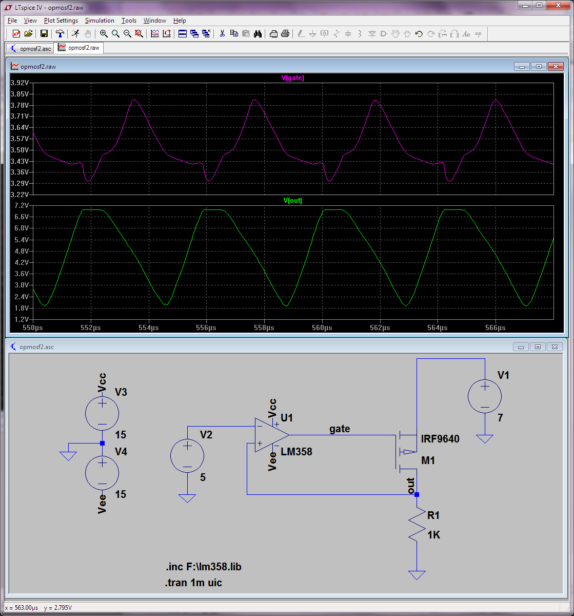
Well, capacitive load is a difficult problem to deal with even in a correctly set-up circuit, but in your circuit [as drawn] you are providing positive feedback to the opamp! This will oscillate like crazy even in simulation... with the same predicted 5Vpp. Yeah the oscillation shape is a bit different in simulation, but what do you expect... no parasitics and LM358 has a rather basic SPICE model.

enter image description here


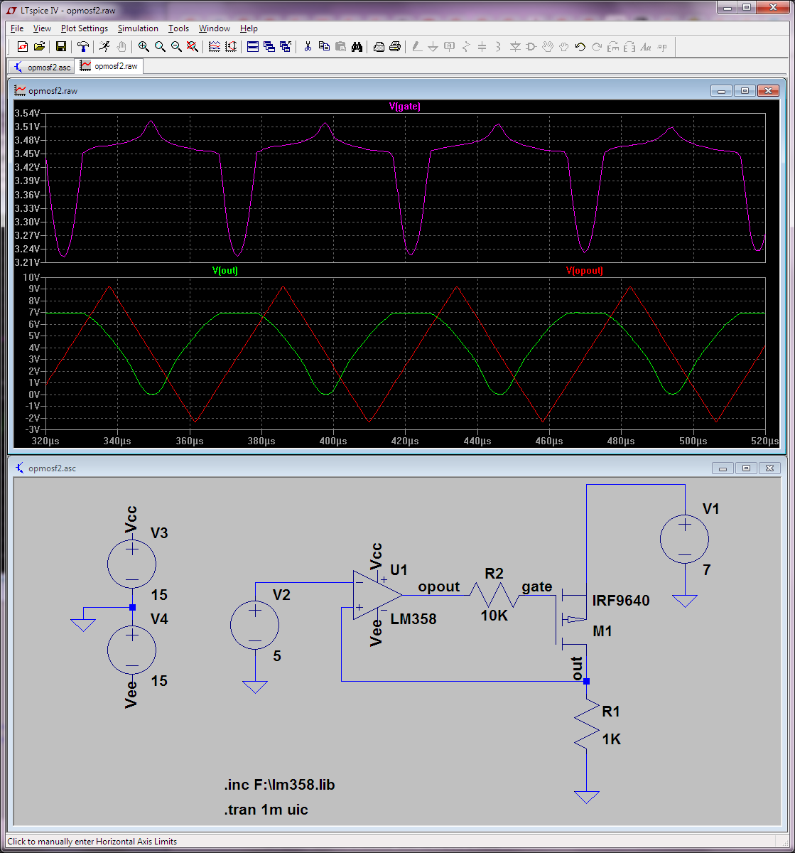
@LvW: I need to think a bit more about what exactly happens but see updated graph with Vgate plotted as well. Clearly it never reaches 5V so the opamp is never seeing actual negative feedback as this design purportedly does. So the opamp works like a comparator basically. There's also some phase shift between these two signals, but I'm not convinced that's the cause of the oscillation, rather I think it's "by design". I've tried adding some big (1K, even 10K) resistor on the gate, and it still oscillates the same.

enter image description here


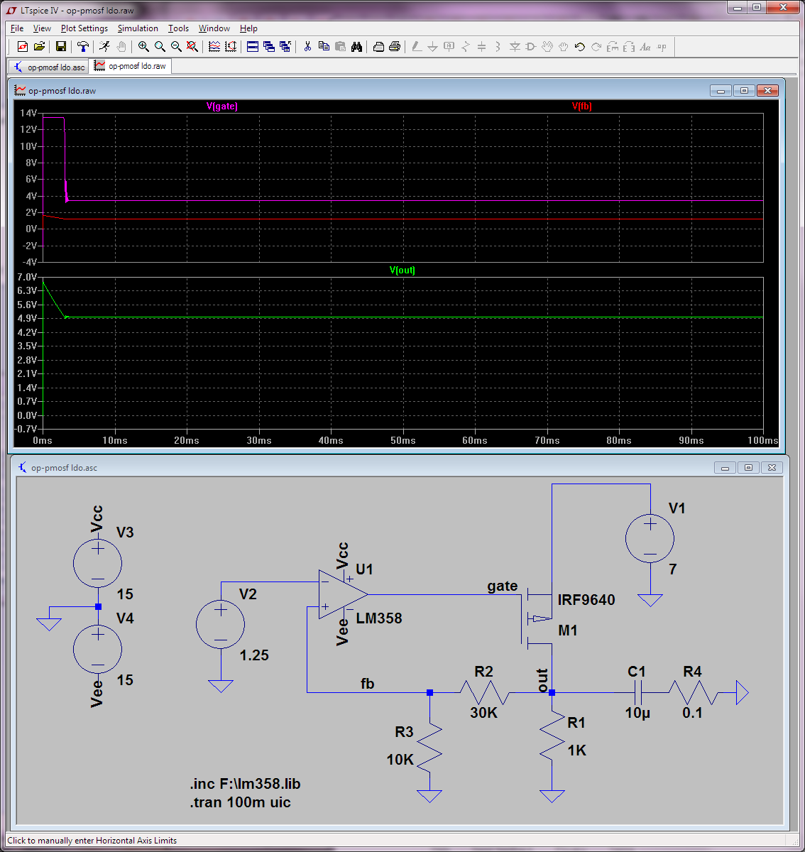
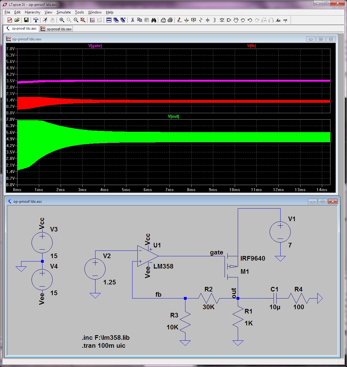
Basically what you're trying to do is design a PMOS LDO! But you're doing it fairly wrong. You need to compensate it with a bypass cap of the right-ish size and ESR! Also, a PMOS LDO would take the feedback through a voltage divider. Here's my amateurish LDO design:

enter image description here

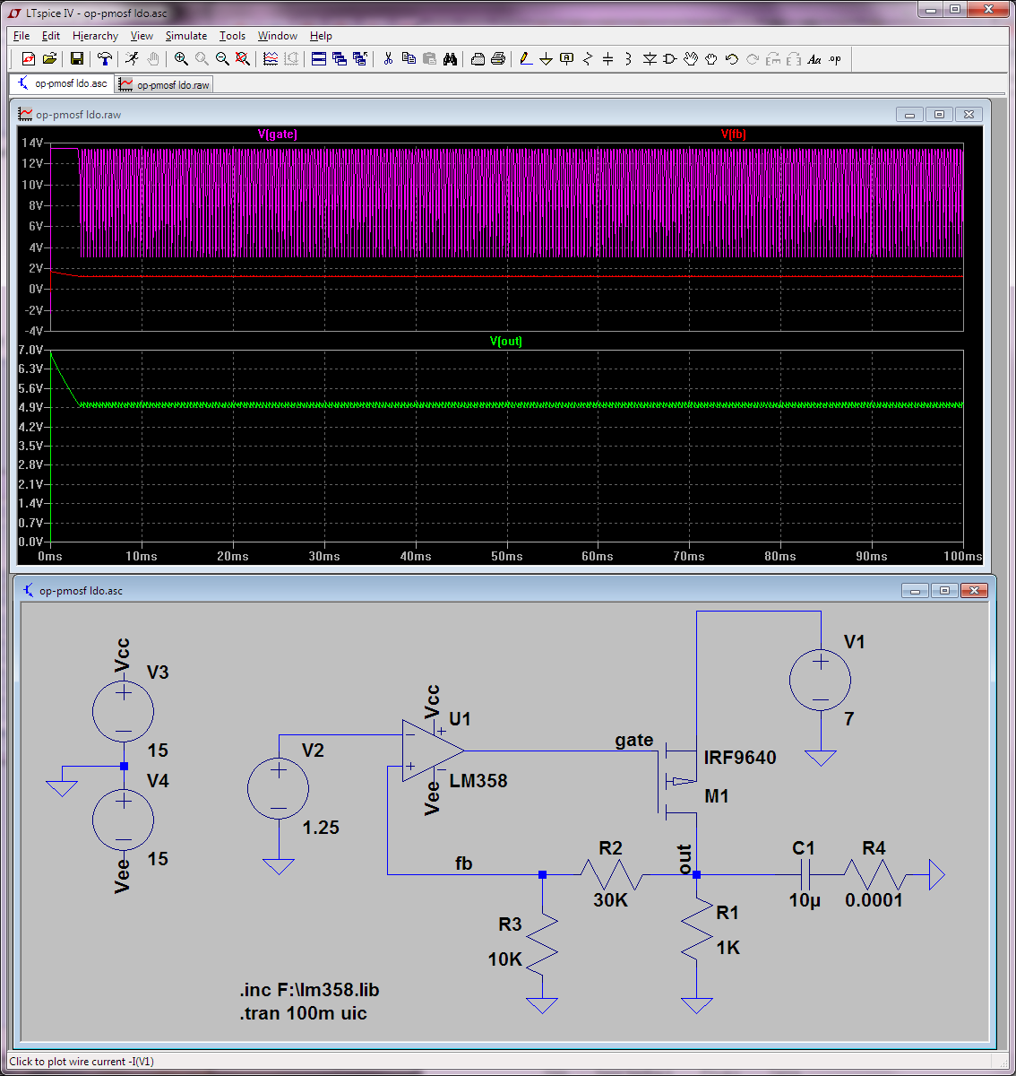
As usual with PMOS LDOs, the output cap ESR is critical and needs to be in a certain band. Look what happens if I lower it, for instance; starts to oscillate:

enter image description here

If ESR is too high, you're again in trouble; well for this (fairly low) load it does have to get pretty high before it oscillates on the other side of the safe band:

enter image description here

Actually, the only critical element in there is that compensation cap. A 10uF one with 0.1ohm ESR appears to work for a fairly large load range from 1K down to 5 ohms (which would give you the 1A sooutput you wanted):

enter image description here

You'd get some bandwidth limitation from cap this cap of course.

Well, capacitive load is a difficult problem to deal with even in a correctly set-up circuit, but in your circuit [as drawn] you are providing positive feedback to the opamp! This will oscillate like crazy even in simulation... with the same predicted 5Vpp. Yeah the oscillation shape is a bit different in simulation, but what do you expect... no parasitics and LM358 has a rather basic SPICE model.

enter image description here


@LvW: I need to think a bit more about what exactly happens but see updated graph with Vgate plotted as well. Clearly it never reaches 5V so the opamp is never seeing actual negative feedback as this design purportedly does. So the opamp works like a comparator basically. There's also some phase shift between these two signals, but I'm not convinced that's the cause of the oscillation, rather I think it's "by design". I've tried adding some big (1K, even 10K) resistor on the gate, and it still oscillates the same.

enter image description here


Basically what you're trying to do is design a PMOS LDO! But you're doing it fairly wrong. You need to compensate it with a bypass cap of the right-ish size and ESR! Also take the feedback through a voltage divider. Here's my amateurish LDO design:

enter image description here

As usual with PMOS LDOs, the output cap ESR is critical and needs to be in a certain band. Look what happens if I lower it, for instance; starts to oscillate:

enter image description here

If ESR is too high, you're again in trouble; well for this (fairly low) load it does have to get pretty high before it oscillates on the other side of the safe band:

enter image description here

Actually, the only critical element there is that compensation cap. A 10uF one with 0.1ohm ESR appears to work for a fairly large load range from 1K to 5 ohms (which would give you the 1A so you wanted):

enter image description here

You'd get some bandwidth limitation from cap this of course.

Note: the following paragraph is somewhat incorrect, in the sense that your idea could (and does) work with some tweaks and in a lot of products, PMOS LDOs in particular; see the subsequent material. I'm leaving this paragraph here though because LvW replied to it.

Well, capacitive load is a difficult problem to deal with even in a correctly set-up circuit, but in your circuit [as drawn] you are providing positive feedback to the opamp! This will oscillate like crazy even in simulation... with the same predicted 5Vpp. Yeah the oscillation shape is a bit different in simulation, but what do you expect... no parasitics and LM358 has a rather basic SPICE model.

enter image description here


@LvW: I need to think a bit more about what exactly happens but see updated graph with Vgate plotted as well. Clearly it never reaches 5V so the opamp is never seeing actual negative feedback as this design purportedly does. So the opamp works like a comparator basically. There's also some phase shift between these two signals, but I'm not convinced that's the cause of the oscillation, rather I think it's "by design". I've tried adding some big (1K, even 10K) resistor on the gate, and it still oscillates the same.

enter image description here


Basically what you're trying to do is design a PMOS LDO! But you're doing it fairly wrong. You need to compensate it with a bypass cap of the right-ish size and ESR! Also, a PMOS LDO would take the feedback through a voltage divider. Here's my amateurish LDO design:

enter image description here

As usual with PMOS LDOs, the output cap ESR is critical and needs to be in a certain band. Look what happens if I lower it, for instance; starts to oscillate:

enter image description here

If ESR is too high, you're again in trouble; well for this load it does have to get pretty high before it oscillates on the other side of the safe band:

enter image description here

Actually, the only critical element in there is that compensation cap. A 10uF one with 0.1ohm ESR appears to work for a fairly large load range from 1K down to 5 ohms (which would give you the 1A output you wanted):

enter image description here

You'd get some bandwidth limitation from this cap of course.

deleted 107 characters in body
Source Link

Well, capacitive load is a difficult problem to deal with even in a correctly set-up circuit, but in your circuit [as drawn] you are providing positive feedback to the opamp! This will oscillate like crazy even in simulation... with the same predicted 5Vpp. Yeah the oscillation shape is a bit different in simulation, but what do you expect... no parasitics and LM358 has a rather basic SPICE model.

enter image description here


@LvW: I need to think a bit more about what exactly happens but see updated graph with Vgate plotted as well. Clearly it never reaches 5V so the opamp is never seeing actual negative feedback as this design purportedly does. So the opamp works like a comparator basically. There's also some phase shift between these two signals, but I'm not convinced that's the cause of the oscillation, rather I think it's "by design". I've tried adding some big (1K, even 10K) resistor on the gate, and it still oscillates the same.

enter image description here


Basically what you're trying to do is design a PMOS LDO! But you're doing it fairly wrong. You need to compensate it with a bypass cap of the right-ish size and ESR! Also take the feedback through a voltage divider. Here's my amateurish LDO design:

enter image description here

As usual with PMOS LDOs, the output cap ESR is critical and needs to be in a certain band. Look what happens if I lower it, for instance; starts to oscillate:

enter image description here

If ESR is too high, you're again in trouble; well for this (fairly low) load it does have to get pretty high before it oscillates on the other side of the safe band:

enter image description here

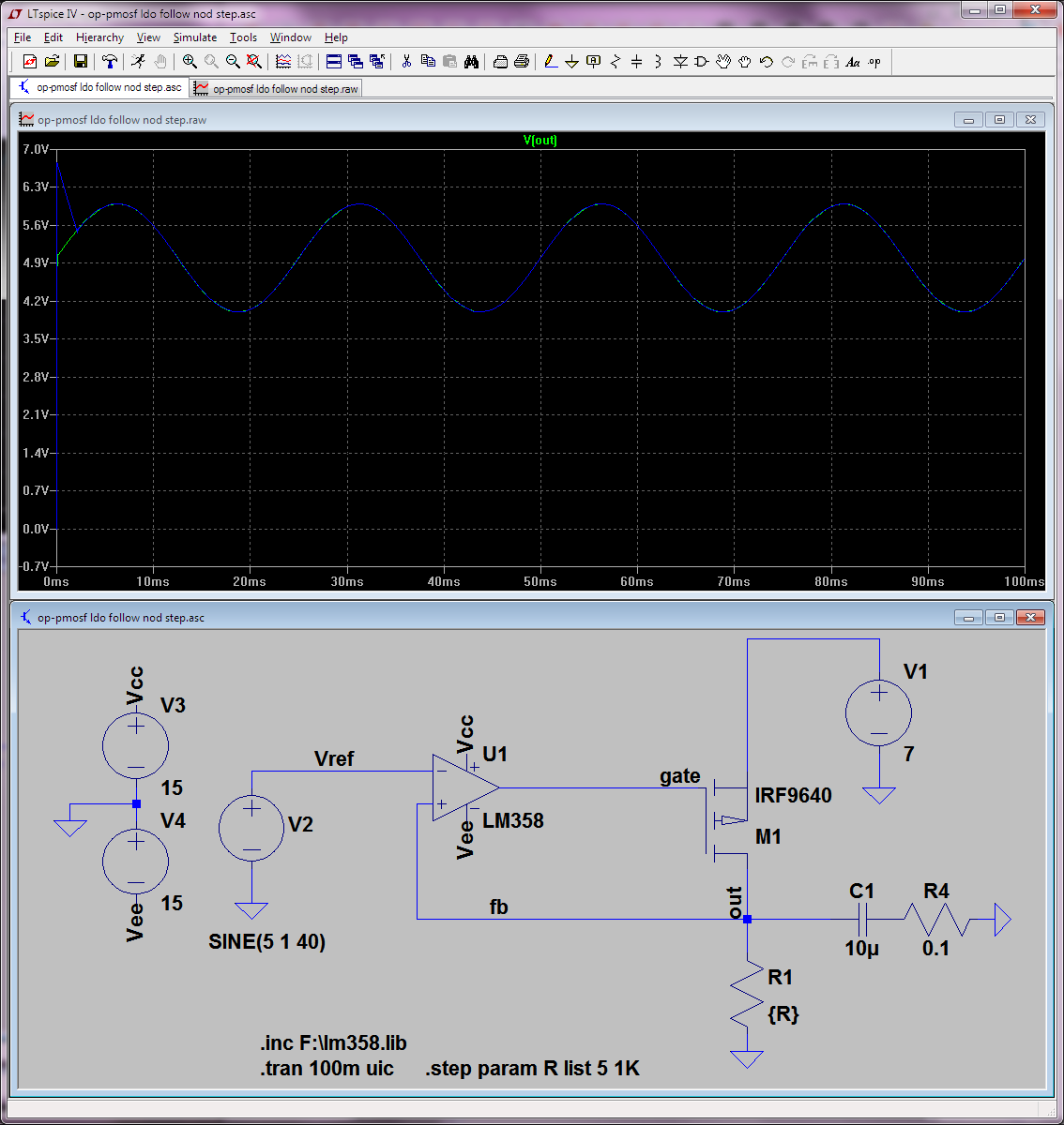
Fairly obviousActually, but for this work as PMOS-LDO-follower (LOL!) you'd now need to take your Vref input signal through a divider as wellthe only critical element there is that compensation cap. It seemsA 10uF one with 0.1ohm ESR appears to have decent linearity inwork for a certain band of vref... but it is certainly one of the most impractical voltage followers designedfairly large load range from 1K to 5 ohms (for arbitrary not DC signals); it does look it could handlewhich would give you the couple of amps1A so you wanted though):

enter image description hereenter image description here

You'd get some bandwidth limitation from cap this of course.

Well, capacitive load is a difficult problem to deal with even in a correctly set-up circuit, but in your circuit [as drawn] you are providing positive feedback to the opamp! This will oscillate like crazy even in simulation... with the same predicted 5Vpp. Yeah the oscillation shape is a bit different in simulation, but what do you expect... no parasitics and LM358 has a rather basic SPICE model.

enter image description here


@LvW: I need to think a bit more about what exactly happens but see updated graph with Vgate plotted as well. Clearly it never reaches 5V so the opamp is never seeing actual negative feedback as this design purportedly does. So the opamp works like a comparator basically. There's also some phase shift between these two signals, but I'm not convinced that's the cause of the oscillation, rather I think it's "by design". I've tried adding some big (1K, even 10K) resistor on the gate, and it still oscillates the same.

enter image description here


Basically what you're trying to do is design a PMOS LDO! But you're doing it fairly wrong. You need to compensate it with a bypass cap of the right-ish size and ESR! Also take the feedback through a voltage divider. Here's my amateurish LDO design:

enter image description here

As usual with PMOS LDOs, the output cap ESR is critical and needs to be in a certain band. Look what happens if I lower it, for instance; starts to oscillate:

enter image description here

If ESR is too high, you're again in trouble; well for this (fairly low) load it does have to get pretty high before it oscillates on the other side of the safe band:

enter image description here

Fairly obvious, but for this work as PMOS-LDO-follower (LOL!) you'd now need to take your Vref input signal through a divider as well. It seems to have decent linearity in a certain band of vref... but it is certainly one of the most impractical voltage followers designed (for arbitrary not DC signals); it does look it could handle the couple of amps you wanted though:

enter image description here

Well, capacitive load is a difficult problem to deal with even in a correctly set-up circuit, but in your circuit [as drawn] you are providing positive feedback to the opamp! This will oscillate like crazy even in simulation... with the same predicted 5Vpp. Yeah the oscillation shape is a bit different in simulation, but what do you expect... no parasitics and LM358 has a rather basic SPICE model.

enter image description here


@LvW: I need to think a bit more about what exactly happens but see updated graph with Vgate plotted as well. Clearly it never reaches 5V so the opamp is never seeing actual negative feedback as this design purportedly does. So the opamp works like a comparator basically. There's also some phase shift between these two signals, but I'm not convinced that's the cause of the oscillation, rather I think it's "by design". I've tried adding some big (1K, even 10K) resistor on the gate, and it still oscillates the same.

enter image description here


Basically what you're trying to do is design a PMOS LDO! But you're doing it fairly wrong. You need to compensate it with a bypass cap of the right-ish size and ESR! Also take the feedback through a voltage divider. Here's my amateurish LDO design:

enter image description here

As usual with PMOS LDOs, the output cap ESR is critical and needs to be in a certain band. Look what happens if I lower it, for instance; starts to oscillate:

enter image description here

If ESR is too high, you're again in trouble; well for this (fairly low) load it does have to get pretty high before it oscillates on the other side of the safe band:

enter image description here

Actually, the only critical element there is that compensation cap. A 10uF one with 0.1ohm ESR appears to work for a fairly large load range from 1K to 5 ohms (which would give you the 1A so you wanted):

enter image description here

You'd get some bandwidth limitation from cap this of course.

edited body
Source Link

Well, capacitive load is a difficult problem to deal with even in a correctly set-up circuit, but in your circuit [as drawn] you are providing positive feedback to the opamp! This will oscillate like crazy even in simulation... with the same predicted 5Vpp. Yeah the oscillation shape is a bit different in simulation, but what do you expect... no parasitics and LM358 has a rather basic SPICE model.

enter image description here


@LvW: I need to think a bit more about what exactly happens but see updated graph with Vgate plotted as well. Clearly it never reaches 5V so the opamp is never seeing actual negative feedback as this design purportedly does. So the opamp works like a comparator basically. There's also some phase shift between these two signals, but I'm not convinced that's the cause of the oscillation, rather I think it's "by design". I've tried adding some big (1K, even 10K) resistor on the gate, and it still oscillates the same.

enter image description here


Basically what you're trying to do is design a PMOS LDO! But you're doing it fairly wrong. You need to compensate it with a bypass cap of the right-ish size and ESR! Also take the feedback through a voltage divider. Here's my amateurish LDO design:

enter image description here

As usual with PMOS LDOs, the output cap ESR is critical and needs to be in a certain band. Look what happens if I lower it, for instance; starts to oscillate:

enter image description here

If ESR is too high, you're again in trouble; well for this (fairly low) load it does have to get pretty high before it oscillates on the other side of the safe band:

enter image description here

Fairly obvious, but for this work as PMOS-LDO-follower (LOL!) you'd now need to take your Vref input signal through a divider as well. It seems to have decent linearity in a certain band of vref... but it is certainly one of the most impractical voltage followers designed (for arbitrary not DC signals); it does look it could handle the couple of amps you wanted though:

enter image description hereenter image description here

Well, capacitive load is a difficult problem to deal with even in a correctly set-up circuit, but in your circuit [as drawn] you are providing positive feedback to the opamp! This will oscillate like crazy even in simulation... with the same predicted 5Vpp. Yeah the oscillation shape is a bit different in simulation, but what do you expect... no parasitics and LM358 has a rather basic SPICE model.

enter image description here


@LvW: I need to think a bit more about what exactly happens but see updated graph with Vgate plotted as well. Clearly it never reaches 5V so the opamp is never seeing actual negative feedback as this design purportedly does. So the opamp works like a comparator basically. There's also some phase shift between these two signals, but I'm not convinced that's the cause of the oscillation, rather I think it's "by design". I've tried adding some big (1K, even 10K) resistor on the gate, and it still oscillates the same.

enter image description here


Basically what you're trying to do is design a PMOS LDO! But you're doing it fairly wrong. You need to compensate it with a bypass cap of the right-ish size and ESR! Also take the feedback through a voltage divider. Here's my amateurish LDO design:

enter image description here

As usual with PMOS LDOs, the output cap ESR is critical and needs to be in a certain band. Look what happens if I lower it, for instance; starts to oscillate:

enter image description here

If ESR is too high, you're again in trouble; well for this (fairly low) load it does have to get pretty high before it oscillates on the other side of the safe band:

enter image description here

Fairly obvious, but for this work as PMOS-LDO-follower (LOL!) you'd now need to take your Vref input signal through a divider as well. It seems to have decent linearity in a certain band of vref... but it is certainly one of the most impractical voltage followers designed (for arbitrary not DC signals); it does look it could handle the couple of amps you wanted though:

enter image description here

added 257 characters in body
Source Link
Loading
added 257 characters in body
Source Link
Loading
added 120 characters in body
Source Link
Loading
added 635 characters in body
Source Link
Loading
added 98 characters in body
Source Link
Loading
added 519 characters in body
Source Link
Loading
Source Link
Loading