added 159 characters in body
Source Link
user16222
user16222

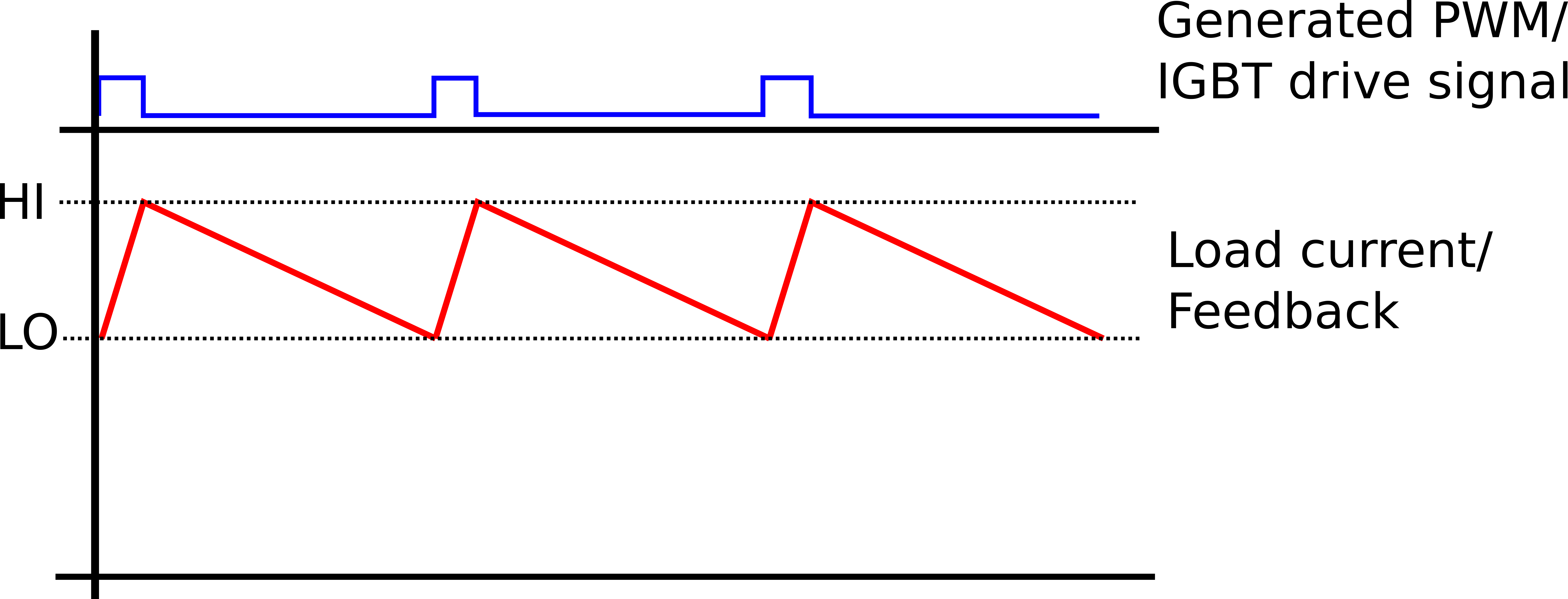
With an inductive load and PWM.

IGBT's are optimised to be Discrete ON or OFF devices and do not have a linear/active region like MOSFET's and BJT's.

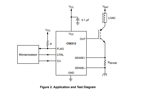
The CS8312 shows an example setup with an inductive load and a sense resistor.

This particular chip works by increasing the threshold by 45%

Changing the CLI pin from a logic low to a logic high increases the FLAG turn on voltage by approximately 45% and the regulation sense voltage by approximately 39% respectively.

Other methods are via simple comparator for hysteresis control or PI controller to then generate a PWM signal that is indirectly used to drive the IGBT

enter image description here

enter image description here

With an inductive load and PWM.

IGBT's are optimised to be Discrete ON or OFF devices and do not have a linear/active region like MOSFET's and BJT's.

The CS8312 shows an example setup with an inductive load and a sense resistor.

This particular chip works by increasing the threshold by 45%

Changing the CLI pin from a logic low to a logic high increases the FLAG turn on voltage by approximately 45% and the regulation sense voltage by approximately 39% respectively.

Other methods are via simple comparator for hysteresis control or PI controller

enter image description here

With an inductive load and PWM.

IGBT's are optimised to be Discrete ON or OFF devices and do not have a linear/active region like MOSFET's and BJT's.

The CS8312 shows an example setup with an inductive load and a sense resistor.

This particular chip works by increasing the threshold by 45%

Changing the CLI pin from a logic low to a logic high increases the FLAG turn on voltage by approximately 45% and the regulation sense voltage by approximately 39% respectively.

Other methods are via simple comparator for hysteresis control or PI controller to then generate a PWM signal that is indirectly used to drive the IGBT
enter image description here

enter image description here

added 106 characters in body
Source Link
user16222
user16222

With an inductive load and PWM.

IGBT's are optimised to be Discrete ON or OFF devices and do not have a linear/active region like MOSFET's and BJT's.

The CS8312 shows an example setup with an inductive load and a sense resistor.

An analogue voltage is provided as a current reference and the current feedback (viaThis particular chip works by increasing the sense resistor) are both fed into a comparator/schmitt to generate PWM.threshold by 45%

Changing the CLI pin from a logic low to a logic high increases the FLAG turn on voltage by approximately 45% and the regulation sense voltage by approximately 39% respectively.

This PWM chop's Vbat and controls the current through the load.Other methods are via simple comparator for hysteresis control or PI controller

enter image description here

With an inductive load and PWM.

IGBT's are optimised to be Discrete ON or OFF devices and do not have a linear/active region like MOSFET's and BJT's.

The CS8312 shows an example setup with an inductive load and a sense resistor.

An analogue voltage is provided as a current reference and the current feedback (via the sense resistor) are both fed into a comparator/schmitt to generate PWM.

This PWM chop's Vbat and controls the current through the load.

enter image description here

With an inductive load and PWM.

IGBT's are optimised to be Discrete ON or OFF devices and do not have a linear/active region like MOSFET's and BJT's.

The CS8312 shows an example setup with an inductive load and a sense resistor.

This particular chip works by increasing the threshold by 45%

Changing the CLI pin from a logic low to a logic high increases the FLAG turn on voltage by approximately 45% and the regulation sense voltage by approximately 39% respectively.

Other methods are via simple comparator for hysteresis control or PI controller

enter image description here

Source Link
user16222
user16222

With an inductive load and PWM.

IGBT's are optimised to be Discrete ON or OFF devices and do not have a linear/active region like MOSFET's and BJT's.

The CS8312 shows an example setup with an inductive load and a sense resistor.

An analogue voltage is provided as a current reference and the current feedback (via the sense resistor) are both fed into a comparator/schmitt to generate PWM.

This PWM chop's Vbat and controls the current through the load.

enter image description here