added comments on power draw
Source Link

Not so much an answer to the power draw, yet, but hereHere is some info on the EC-LED-19A circuit.

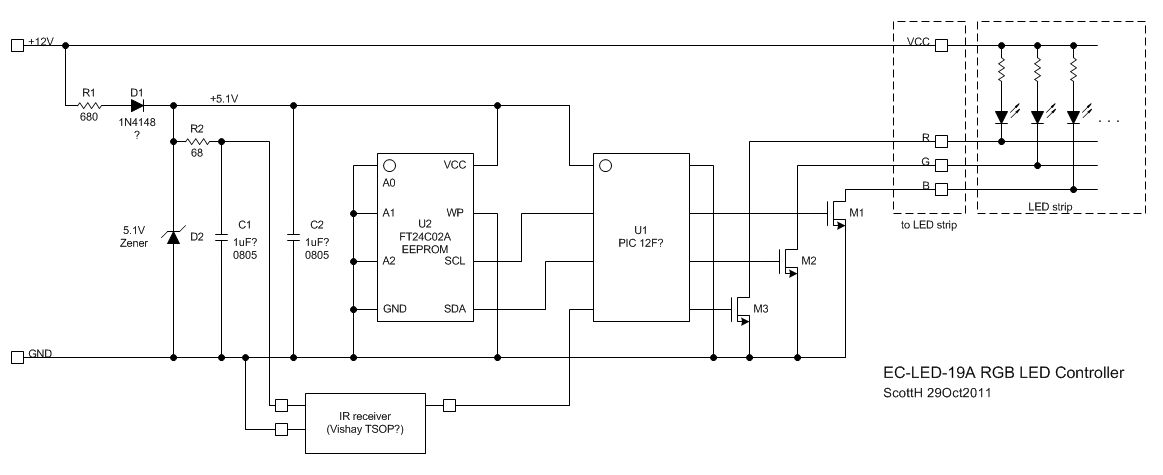
The controller is modulating the ground side of the R, G and B lines. The diodes are connected common anode to supply, and the grounds are switched through the (presumably) MOS switches (WFA0N). You are corrected about the EEPROM, and the uC pinout matches a PIC 12F275 or similar. I'm not sure why they used the external EEPROM when the PIC uC's allow you to write data back into the internal EEPROM in the part... perhaps it's a cheaper write-once (PROM) uC? The board appears to use a simple 5.1V Zener diode for a cheap regulator. This one has empty footprints for a 7805 or similar voltage regulator, but for this application a simple resistor (680 ohm) and Zener are fine. There's a reverse protection diode, as well.

[edit - I've added a schematic diagram, below.]

For most colors, two of the lines are either constantly on or off and the third is pulse-width modulated at a 500Hz rate. (measured with an o-scope)

There's a similar circuit on Instructables here: http://www.instructables.com/id/How-to-fit-LED-kitchen-lights-with-fade-effect/step2/Fader/

I ordered mine off eBay... and I was hoping to have a continuously adjustable level of each color, so I'll probably put together my own board for this... though I could just replace the uC with one with a similar pinout and leave a two-wire programming connector in there.

As to the power draw, for the "white" setting, it looks like two of the strings (blue and green, I think) are at full power while the other (red) is pulse width modulated with less than 50% duty cycle (more like 30%). So that might explain why at full brightness on the white setting you'd seeing about 75% of full current. As to the larger difference from 6A down to 2A, the strip is spec'd at 14.4W/m at 12V, or 1.2A/m or 6A total for your 5m strip. I'd suspect the drop in voltage down the strip may have a lot to do with this, as others have suggested, combined with the PWM cycling on one string.

-Scott enter image description here
Not so much an answer to the power draw, yet, but here is some info on the EC-LED-19A circuit.

The controller is modulating the ground side of the R, G and B lines. The diodes are connected common anode to supply, and the grounds are switched through the (presumably) MOS switches (WFA0N). You are corrected about the EEPROM, and the uC pinout matches a PIC 12F275 or similar. I'm not sure why they used the external EEPROM when the PIC uC's allow you to write data back into the internal EEPROM in the part... perhaps it's a cheaper write-once (PROM) uC? The board appears to use a simple 5.1V Zener diode for a cheap regulator. This one has empty footprints for a 7805 or similar voltage regulator, but for this application a simple resistor (680 ohm) and Zener are fine. There's a reverse protection diode, as well.

[edit - I've added a schematic diagram, below.]

For most colors, two of the lines are either constantly on or off and the third is pulse-width modulated at a 500Hz rate. (measured with an o-scope)

There's a similar circuit on Instructables here: http://www.instructables.com/id/How-to-fit-LED-kitchen-lights-with-fade-effect/step2/Fader/

I ordered mine off eBay... and I was hoping to have a continuously adjustable level of each color, so I'll probably put together my own board for this... though I could just replace the uC with one with a similar pinout and leave a two-wire programming connector in there.

-Scott enter image description here

Here is some info on the EC-LED-19A circuit.

The controller is modulating the ground side of the R, G and B lines. The diodes are connected common anode to supply, and the grounds are switched through the (presumably) MOS switches (WFA0N). You are corrected about the EEPROM, and the uC pinout matches a PIC 12F275 or similar. I'm not sure why they used the external EEPROM when the PIC uC's allow you to write data back into the internal EEPROM in the part... perhaps it's a cheaper write-once (PROM) uC? The board appears to use a simple 5.1V Zener diode for a cheap regulator. This one has empty footprints for a 7805 or similar voltage regulator, but for this application a simple resistor (680 ohm) and Zener are fine. There's a reverse protection diode, as well.

[edit - I've added a schematic diagram, below.]

For most colors, two of the lines are either constantly on or off and the third is pulse-width modulated at a 500Hz rate. (measured with an o-scope)

There's a similar circuit on Instructables here: http://www.instructables.com/id/How-to-fit-LED-kitchen-lights-with-fade-effect/step2/Fader/

I ordered mine off eBay... and I was hoping to have a continuously adjustable level of each color, so I'll probably put together my own board for this... though I could just replace the uC with one with a similar pinout and leave a two-wire programming connector in there.

As to the power draw, for the "white" setting, it looks like two of the strings (blue and green, I think) are at full power while the other (red) is pulse width modulated with less than 50% duty cycle (more like 30%). So that might explain why at full brightness on the white setting you'd seeing about 75% of full current. As to the larger difference from 6A down to 2A, the strip is spec'd at 14.4W/m at 12V, or 1.2A/m or 6A total for your 5m strip. I'd suspect the drop in voltage down the strip may have a lot to do with this, as others have suggested, combined with the PWM cycling on one string.

-Scott enter image description here

added a schematic of the EC-LED-19A board
Source Link

Not so much an answer to the power draw, yet, but here is some info on the EC-LED-19A circuit.

The controller is modulating the ground side of the R, G and B lines. The diodes are connected common anode to supply, and the grounds are switched through the (presumably) MOS switches (WFA0N). You are corrected about the EEPROM, and the uC pinout matches a PIC 12F275 or similar. I'm not sure why they used the external EEPROM when the PIC uC's allow you to write data back into the internal EEPROM in the part... perhaps it's a cheaper write-once (PROM) uC? The board appears to use a simple 5.1V Zener diode for a cheap regulator. This one has empty footprints for a 7805 or similar voltage regulator, but for this application a simple resistor (680 ohm) and Zener are fine. There's a reverse protection diode, as well.

[edit - I've added a schematic diagram, below.]

For most colors, two of the lines are either constantly on or off and the third is pulse-width modulated at a 500Hz rate. (measured with an o-scope)

There's a similar circuit on Instructables here: http://www.instructables.com/id/How-to-fit-LED-kitchen-lights-with-fade-effect/step2/Fader/

I ordered mine off eBay... and I was hoping to have a continuously adjustable level of each color, so I'll probably put together my own board for this... though I could just replace the uC with one with a similar pinout and leave a two-wire programming connector in there.

-Scott enter image description here

Not so much an answer to the power draw, yet, but here is some info on the EC-LED-19A circuit.

The controller is modulating the ground side of the R, G and B lines. The diodes are connected common anode to supply, and the grounds are switched through the (presumably) MOS switches (WFA0N). You are corrected about the EEPROM, and the uC pinout matches a PIC 12F275 or similar. I'm not sure why they used the external EEPROM when the PIC uC's allow you to write data back into the internal EEPROM in the part... perhaps it's a cheaper write-once (PROM) uC? The board appears to use a simple 5.1V Zener diode for a cheap regulator. This one has empty footprints for a 7805 or similar voltage regulator, but for this application a simple resistor (680 ohm) and Zener are fine. There's a reverse protection diode, as well.

For most colors, two of the lines are either constantly on or off and the third is pulse-width modulated at a 500Hz rate. (measured with an o-scope)

There's a similar circuit on Instructables here: http://www.instructables.com/id/How-to-fit-LED-kitchen-lights-with-fade-effect/step2/Fader/

I ordered mine off eBay... and I was hoping to have a continuously adjustable level of each color, so I'll probably put together my own board for this... though I could just replace the uC with one with a similar pinout and leave a two-wire programming connector in there.

-Scott

Not so much an answer to the power draw, yet, but here is some info on the EC-LED-19A circuit.

The controller is modulating the ground side of the R, G and B lines. The diodes are connected common anode to supply, and the grounds are switched through the (presumably) MOS switches (WFA0N). You are corrected about the EEPROM, and the uC pinout matches a PIC 12F275 or similar. I'm not sure why they used the external EEPROM when the PIC uC's allow you to write data back into the internal EEPROM in the part... perhaps it's a cheaper write-once (PROM) uC? The board appears to use a simple 5.1V Zener diode for a cheap regulator. This one has empty footprints for a 7805 or similar voltage regulator, but for this application a simple resistor (680 ohm) and Zener are fine. There's a reverse protection diode, as well.

[edit - I've added a schematic diagram, below.]

For most colors, two of the lines are either constantly on or off and the third is pulse-width modulated at a 500Hz rate. (measured with an o-scope)

There's a similar circuit on Instructables here: http://www.instructables.com/id/How-to-fit-LED-kitchen-lights-with-fade-effect/step2/Fader/

I ordered mine off eBay... and I was hoping to have a continuously adjustable level of each color, so I'll probably put together my own board for this... though I could just replace the uC with one with a similar pinout and leave a two-wire programming connector in there.

-Scott enter image description here

clarification
Source Link

Not so much an answer to the power draw, yet, but here is some info on the EC-LED-19A circuit.

The controller is modulating the ground side of the R, G and B lines. The diodes are connected common anode to supply, and the grounds are switched through the (presumably) MOS switches (WFA0N). You are corrected about the EEPROM, and the uC pinout matches a PIC 12F275 or similar. I'm not sure why they used the external EEPROM when the PIC uC's allow you to write data back into the internal EEPROM in the part... perhaps it's a cheaper write-once (PROM) uC? The board appears to use a simple 5.1V Zener diode for a cheap regulator. This one has empty footprints for a 7805 or similar voltage regulator, but for this application a simple resistor (680 ohm) and Zener are fine. There's a reverse protection diode, as well.

For most colors, two of the lines are either constantly on or off and the third is pulse-width modulated at a 500Hz rate. (measured with an o-scope)

There's a similar circuit on Instructables here: http://www.instructables.com/id/How-to-fit-LED-kitchen-lights-with-fade-effect/step2/Fader/

I ordered mine off eBay... and I was hoping to have a continuously adjustable level of each color, so I'll probably put together my own board for this... though I could just replace the uC with one with a similar pinout and leave a two-wire programming connector in there.   

-Scott

The controller is modulating the ground side of the R, G and B lines. The diodes are connected common anode to supply, and the grounds are switched through the (presumably) MOS switches (WFA0N).

For most colors, two of the lines are either constantly on or off and the third is pulse-width modulated at a 500Hz rate.

There's a similar circuit on Instructables here: http://www.instructables.com/id/How-to-fit-LED-kitchen-lights-with-fade-effect/step2/Fader/

I ordered mine off eBay... and I was hoping to have a continuously adjustable level of each color, so I'll probably put together my own board for this... though I could just replace the uC with one with a similar pinout and leave a two-wire programming connector in there.  -Scott

Not so much an answer to the power draw, yet, but here is some info on the EC-LED-19A circuit.

The controller is modulating the ground side of the R, G and B lines. The diodes are connected common anode to supply, and the grounds are switched through the (presumably) MOS switches (WFA0N). You are corrected about the EEPROM, and the uC pinout matches a PIC 12F275 or similar. I'm not sure why they used the external EEPROM when the PIC uC's allow you to write data back into the internal EEPROM in the part... perhaps it's a cheaper write-once (PROM) uC? The board appears to use a simple 5.1V Zener diode for a cheap regulator. This one has empty footprints for a 7805 or similar voltage regulator, but for this application a simple resistor (680 ohm) and Zener are fine. There's a reverse protection diode, as well.

For most colors, two of the lines are either constantly on or off and the third is pulse-width modulated at a 500Hz rate. (measured with an o-scope)

There's a similar circuit on Instructables here: http://www.instructables.com/id/How-to-fit-LED-kitchen-lights-with-fade-effect/step2/Fader/

I ordered mine off eBay... and I was hoping to have a continuously adjustable level of each color, so I'll probably put together my own board for this... though I could just replace the uC with one with a similar pinout and leave a two-wire programming connector in there. 

-Scott

Source Link
Loading