Tweeted twitter.com/#!/StackElectronix/status/140208811075055616
added 168 characters in body
Source Link
Majenko
  • 56.4k
  • 9
  • 106
  • 190

I am trying to create a circuit which will allow me to scale and offset a voltage (be it AC or DC) to within the range of the Arduino ADC.

The voltage could be anything between + and - 250V, but I also need to have good sensitivity over lower voltage ranges too.

To this end I am looking at a circuit whereby you can vary the voltage range that it expects the input to be and amplify/attenuate it accordingly. How I will be making the decision and setting the different gains is for another topic for now. I am only interested in the scaling and offsetting at the moment.

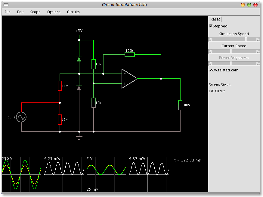
So far I have come up with this circuit:
enter image description here

Which appears to do just what I want for the +/- 250V range. I don't know how "safe" this circuit is, and if I am endangering any of the components with the 250V or not. The graphs at the bottom are (left to right) the input voltage, the power consumption of the bottom 10M resistor, the voltage across the 100M resistor (which is simulating the Arduino ADC input) and the power consumption of the upper 10M resistor.

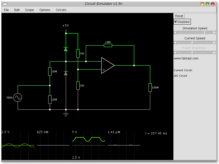
Now, if I drop the input voltage to just +/- 2.5V and tweak the op-amp feedback resistor accordingly, for some reason the offset voltage the op-amp is adding jumps right up. I don't know for sure if this is the fault of the simulator I am using, or if it is really what will happen, as I haven't yet breadboarded this circuit (I guess that's the next stage).

This is the output from the 2.5V version:
enter image description here

You can see how the offset has jumped up and the output is clipping massively.

If I drop the lower 10K resistor to the virtual ground offset voltage divider to just 3.3K it compensates, but that's not nice - I would like to just vary the one resistor.

The op-amp is (will be) a 5V single supply rail-to-rail I/O one.

The two diodes are to protect the input of the op-amp against over voltage - I don't know if this circuit strictly needs them, but I guess it doesn't hurt to have them there.

Also, I don't know if the resistor values are quite what I want - I chose them to keep the power consumption right down and the impedance right up. I don't want them to impact the frequency response of the circuit more than I can help - the input waveform could be anything from DC up to around 500KHz or so, and I need that reproducing at the ADC end as faithfully as I can. (I know the Arduino can only really sample at lower speeds than that, but the Arduino is just for experimenting - the final system will use a dsPIC with 1.1Msps ADC).

So, what can I do to A) get a more stable offset, B) allow the varying of the input sensitivity without nuking either the op-amp or the ADC, and C) make the circuit safe to connect to, for example, a European mains voltage?

I am trying to create a circuit which will allow me to scale and offset a voltage (be it AC or DC) to within the range of the Arduino ADC.

The voltage could be anything between + and - 250V, but I also need to have good sensitivity over lower voltage ranges too.

To this end I am looking at a circuit whereby you can vary the voltage range that it expects the input to be and amplify/attenuate it accordingly. How I will be making the decision and setting the different gains is for another topic for now. I am only interested in the scaling and offsetting at the moment.

So far I have come up with this circuit:

enter image description here

Which appears to do just what I want for the +/- 250V range. I don't know how "safe" this circuit is, and if I am endangering any of the components with the 250V or not. The graphs at the bottom are (left to right) the input voltage, the power consumption of the bottom 10M resistor, the voltage across the 100M resistor (which is simulating the Arduino ADC input) and the power consumption of the upper 10M resistor.

Now, if I drop the input voltage to just +/- 2.5V and tweak the op-amp feedback resistor accordingly, for some reason the offset voltage the op-amp is adding jumps right up. I don't know for sure if this is the fault of the simulator I am using, or if it is really what will happen, as I haven't yet breadboarded this circuit (I guess that's the next stage).

This is the output from the 2.5V version:

enter image description here

You can see how the offset has jumped up and the output is clipping massively.

If I drop the lower 10K resistor to the virtual ground offset voltage divider to just 3.3K it compensates, but that's not nice - I would like to just vary the one resistor.

The op-amp is (will be) a 5V single supply rail-to-rail I/O one.

The two diodes are to protect the input of the op-amp against over voltage - I don't know if this circuit strictly needs them, but I guess it doesn't hurt to have them there.

Also, I don't know if the resistor values are quite what I want - I chose them to keep the power consumption right down and the impedance right up. I don't want them to impact the frequency response of the circuit more than I can help - the input waveform could be anything from DC up to around 500KHz or so, and I need that reproducing at the ADC end as faithfully as I can.

So, what can I do to A) get a more stable offset, B) allow the varying of the input sensitivity without nuking either the op-amp or the ADC, and C) make the circuit safe to connect to, for example, a European mains voltage?

I am trying to create a circuit which will allow me to scale and offset a voltage (be it AC or DC) to within the range of the Arduino ADC.

The voltage could be anything between + and - 250V, but I also need to have good sensitivity over lower voltage ranges too.

To this end I am looking at a circuit whereby you can vary the voltage range that it expects the input to be and amplify/attenuate it accordingly. How I will be making the decision and setting the different gains is for another topic for now. I am only interested in the scaling and offsetting at the moment.

So far I have come up with this circuit:

enter image description here

Which appears to do just what I want for the +/- 250V range. I don't know how "safe" this circuit is, and if I am endangering any of the components with the 250V or not. The graphs at the bottom are (left to right) the input voltage, the power consumption of the bottom 10M resistor, the voltage across the 100M resistor (which is simulating the Arduino ADC input) and the power consumption of the upper 10M resistor.

Now, if I drop the input voltage to just +/- 2.5V and tweak the op-amp feedback resistor accordingly, for some reason the offset voltage the op-amp is adding jumps right up. I don't know for sure if this is the fault of the simulator I am using, or if it is really what will happen, as I haven't yet breadboarded this circuit (I guess that's the next stage).

This is the output from the 2.5V version:

enter image description here

You can see how the offset has jumped up and the output is clipping massively.

If I drop the lower 10K resistor to the virtual ground offset voltage divider to just 3.3K it compensates, but that's not nice - I would like to just vary the one resistor.

The op-amp is (will be) a 5V single supply rail-to-rail I/O one.

The two diodes are to protect the input of the op-amp against over voltage - I don't know if this circuit strictly needs them, but I guess it doesn't hurt to have them there.

Also, I don't know if the resistor values are quite what I want - I chose them to keep the power consumption right down and the impedance right up. I don't want them to impact the frequency response of the circuit more than I can help - the input waveform could be anything from DC up to around 500KHz or so, and I need that reproducing at the ADC end as faithfully as I can. (I know the Arduino can only really sample at lower speeds than that, but the Arduino is just for experimenting - the final system will use a dsPIC with 1.1Msps ADC).

So, what can I do to A) get a more stable offset, B) allow the varying of the input sensitivity without nuking either the op-amp or the ADC, and C) make the circuit safe to connect to, for example, a European mains voltage?

Source Link
Majenko
  • 56.4k
  • 9
  • 106
  • 190

Combined ADC scaling and offset with variable input voltage ranges

I am trying to create a circuit which will allow me to scale and offset a voltage (be it AC or DC) to within the range of the Arduino ADC.

The voltage could be anything between + and - 250V, but I also need to have good sensitivity over lower voltage ranges too.

To this end I am looking at a circuit whereby you can vary the voltage range that it expects the input to be and amplify/attenuate it accordingly. How I will be making the decision and setting the different gains is for another topic for now. I am only interested in the scaling and offsetting at the moment.

So far I have come up with this circuit:

enter image description here

Which appears to do just what I want for the +/- 250V range. I don't know how "safe" this circuit is, and if I am endangering any of the components with the 250V or not. The graphs at the bottom are (left to right) the input voltage, the power consumption of the bottom 10M resistor, the voltage across the 100M resistor (which is simulating the Arduino ADC input) and the power consumption of the upper 10M resistor.

Now, if I drop the input voltage to just +/- 2.5V and tweak the op-amp feedback resistor accordingly, for some reason the offset voltage the op-amp is adding jumps right up. I don't know for sure if this is the fault of the simulator I am using, or if it is really what will happen, as I haven't yet breadboarded this circuit (I guess that's the next stage).

This is the output from the 2.5V version:

enter image description here

You can see how the offset has jumped up and the output is clipping massively.

If I drop the lower 10K resistor to the virtual ground offset voltage divider to just 3.3K it compensates, but that's not nice - I would like to just vary the one resistor.

The op-amp is (will be) a 5V single supply rail-to-rail I/O one.

The two diodes are to protect the input of the op-amp against over voltage - I don't know if this circuit strictly needs them, but I guess it doesn't hurt to have them there.

Also, I don't know if the resistor values are quite what I want - I chose them to keep the power consumption right down and the impedance right up. I don't want them to impact the frequency response of the circuit more than I can help - the input waveform could be anything from DC up to around 500KHz or so, and I need that reproducing at the ADC end as faithfully as I can.

So, what can I do to A) get a more stable offset, B) allow the varying of the input sensitivity without nuking either the op-amp or the ADC, and C) make the circuit safe to connect to, for example, a European mains voltage?