Added detail from the comments; clarified title; fixed typo; added [mains] and [voltage-measurement]; removed [ac], [dc], [bias] (obsolete)
Source Link

What is the correct way How to add a directmeasure mains AC voltage andwith an alternating voltageADC from a microcontroller?

I want to measure the Mains voltage (230V/50Hz) using an ADC channel from a microcontroller.

This is my current approach ...

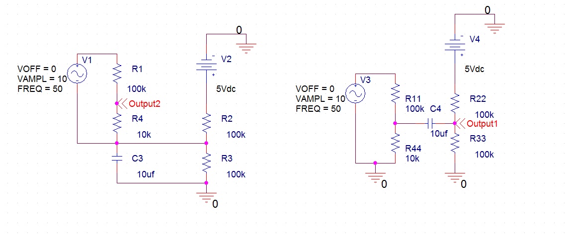
Below I have two schematics that add two voltages (one direct, one alternating).

Added to that, the both the AC and DC signals are going through voltage divider, but that isn't important.

I'm guessing that the output voltage on the second schematic is lower because of the impendaceimpedance of the capacitor?   

Schematics

What is the correct way to add a direct voltage and an alternating voltage

Below I have two schematics that add two voltages (one direct, one alternating).

Added to that, the both the AC and DC signals are going through voltage divider, but that isn't important.

I'm guessing that the output voltage on the second schematic is lower because of the impendace of the capacitor?  Schematics

How to measure mains AC voltage with an ADC from a microcontroller?

I want to measure the Mains voltage (230V/50Hz) using an ADC channel from a microcontroller.

This is my current approach ...

Below I have two schematics that add two voltages (one direct, one alternating).

Added to that, the both the AC and DC signals are going through voltage divider, but that isn't important.

I'm guessing that the output voltage on the second schematic is lower because of the impedance of the capacitor? 

Schematics

Bumped by Community user
Source Link
C Cezar
  • 75
  • 2
  • 5
  • 10

What is the correct way to add a direct voltage and an alternating voltage

Below I have two schematics that add two voltages (one direct, one alternating).

Added to that, the both the AC and DC signals are going through voltage divider, but that isn't important.

I'm guessing that the output voltage on the second schematic is lower because of the impendace of the capacitor? Schematics