Commonmark migration
Source Link

LED Impedance is the differential rise of V/I we call ESR or Effective Series Resistance. It is not 20.3V/350mA=58 Ohms. It is very low so depending on power rating, I will be zero until about 87% of the Vf rated where the threshold occurs. The it rises dynamically until saturation then linearly due to ESR, the bulk resistance of the junctions.

If your part is a White LED chip or module and is rated for 5W with a CC drop of about 20.3V but you are driving it with 7W, then it will be too hot to touch.

The assumption for power LEDs is approx. 3V drop per LED or 7LED in series here. it could be an array or a single string 7S which results in approx. 21 V but will drop in voltage as junction temp rises. Junction temp can be computed from this.

As far as equivalent series resistance, it depends on the differential change in V vs I or the ESR of the LED.

Normally ESR is inverse to power rating per chip and 7 chips in series will have 7x the ESR. assuming 7S and 5W total, according to my experience, the ESR would be 1/Pd * Ns or about 1.4 Ohms or less.

If there were only 6S , rated for 5W , the Vf could be ~18-20V with even more spread possible @250mA with an ESR of 1 Ohm +/-50% thus an extra 100mA would raise Vf by another 150mV to 20.2V which is close to your result.


If what you indicated for this LED is true, it needs a current source of 5/7 *350mA or 250mA

enter image description here

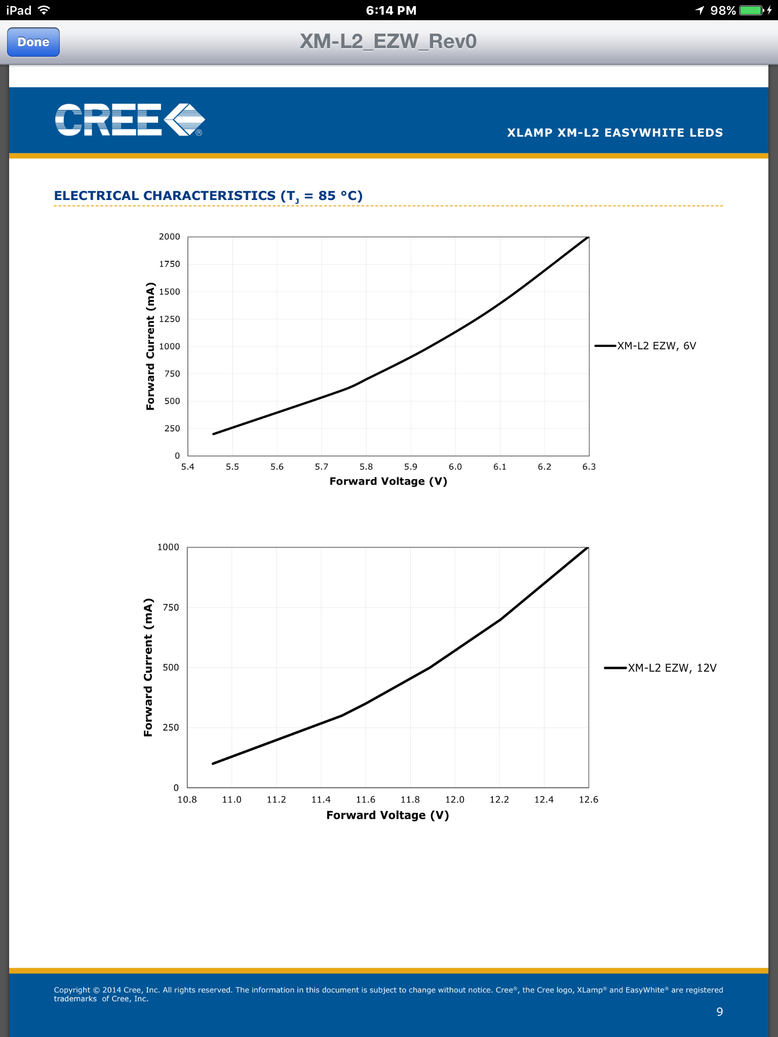
  • Here is a random power LED chosen in 12V range rated at 350mA from Cree
  • The lower curve indicates typ. Vf @350mA ~11.68V (375mA is mid axis)
  • Checking the linear slope at 350mA, on 12V part , I measure slope and ESR @25'C of (11.9-11.4V)/250mA = 2 Ohm. **notice how linear this region is ** around nom. current @ rated power
  • using the ignored quadratic part , it contributes n*24mV/350mA dynamic resistance which appears to be much smaller than actual ESR from contact bulk linear resistance.
  • The contact size is also related to dissipation rating and this is how I use ESR*Pd as a Figure of Merit in quality (lower is better) series ESR must be added but this is a 4 chip LED with options for 2S2P @6V or 4S1P @ 12V

LED Impedance is the differential rise of V/I we call ESR or Effective Series Resistance. It is not 20.3V/350mA=58 Ohms. It is very low so depending on power rating, I will be zero until about 87% of the Vf rated where the threshold occurs. The it rises dynamically until saturation then linearly due to ESR, the bulk resistance of the junctions.

If your part is a White LED chip or module and is rated for 5W with a CC drop of about 20.3V but you are driving it with 7W, then it will be too hot to touch.

The assumption for power LEDs is approx. 3V drop per LED or 7LED in series here. it could be an array or a single string 7S which results in approx. 21 V but will drop in voltage as junction temp rises. Junction temp can be computed from this.

As far as equivalent series resistance, it depends on the differential change in V vs I or the ESR of the LED.

Normally ESR is inverse to power rating per chip and 7 chips in series will have 7x the ESR. assuming 7S and 5W total, according to my experience, the ESR would be 1/Pd * Ns or about 1.4 Ohms or less.

If there were only 6S , rated for 5W , the Vf could be ~18-20V with even more spread possible @250mA with an ESR of 1 Ohm +/-50% thus an extra 100mA would raise Vf by another 150mV to 20.2V which is close to your result.

If what you indicated for this LED is true, it needs a current source of 5/7 *350mA or 250mA

enter image description here

  • Here is a random power LED chosen in 12V range rated at 350mA from Cree
  • The lower curve indicates typ. Vf @350mA ~11.68V (375mA is mid axis)
  • Checking the linear slope at 350mA, on 12V part , I measure slope and ESR @25'C of (11.9-11.4V)/250mA = 2 Ohm. **notice how linear this region is ** around nom. current @ rated power
  • using the ignored quadratic part , it contributes n*24mV/350mA dynamic resistance which appears to be much smaller than actual ESR from contact bulk linear resistance.
  • The contact size is also related to dissipation rating and this is how I use ESR*Pd as a Figure of Merit in quality (lower is better) series ESR must be added but this is a 4 chip LED with options for 2S2P @6V or 4S1P @ 12V
added 776 characters in body
Source Link
D.A.S.
  • 148k
  • 3
  • 56
  • 190

LED Impedance is the differential rise of V/I we call ESR or Effective Series Resistance. It is not 20.3V/350mA=58 Ohms. It is very low so depending on power rating, I will be zero until about 87% of the Vf rated where the threshold occurs. The it rises dynamically until saturation then linearly due to ESR, the bulk resistance of the junctions.

If your part is a White LED chip or module and is rated for 5W with a CC drop of about 20.3V but you are driving it with 7W, then it will be too hot to touch.

The assumption for power LEDs is approx. 3V drop per LED or 7LED in series here. it could be an array or a single string 7S which results in approx. 21 V but will drop in voltage as junction temp rises. Junction temp can be computed from this.

As far as equivalent series resistance, it depends on the differential change in V vs I or the ESR of the LED.

Normally ESR is inverse to power rating per chip and 7 chips in series will have 7x the ESR. assuming 7S and 5W total, according to my experience, the ESR would be 1/Pd * Ns or about 1.4 Ohms or less.

If there were only 6S , rated for 5W , the Vf could be ~18-20V with even more spread possible @250mA with an ESR of 1 Ohm +/-50% thus an extra 100mA would raise Vf by another 150mV to 20.2V which is close to your result.

If what you indicated for this LED is true, it needs a current source of 5/7 *350mA or 250mA

enter image description here

  • Here is a random power LED chosen in 12V range rated at 350mA from Cree
  • The lower curve indicates typ. Vf @350mA ~11.68V (375mA is mid axis)
  • Checking the linear slope at 350mA, on 12V part , I measure slope and ESR @25'C of (11.9-11.4V)/250mA = 2 Ohm. **notice how linear this region is ** around nom. current @ rated power
  • using the ignored quadratic part , it contributes n*24mV/350mA dynamic resistance which appears to be much smaller than actual ESR from contact bulk linear resistance.
  • The contact size is also related to dissipation rating and this is how I use ESR*Pd as a Figure of Merit in quality (lower is better) series ESR must be added but this is a 4 chip LED with options for 2S2P @6V or 4S1P @ 12V

LED Impedance is the differential rise of V/I we call ESR or Effective Series Resistance. It is not 20.3V/350mA=58 Ohms. It is very low so depending on power rating, I will be zero until about 87% of the Vf rated where the threshold occurs. The it rises dynamically until saturation then linearly due to ESR, the bulk resistance of the junctions.

If your part is a White LED chip or module and is rated for 5W with a CC drop of about 20.3V but you are driving it with 7W, then it will be too hot to touch.

The assumption for power LEDs is approx. 3V drop per LED or 7LED in series here. it could be an array or a single string 7S which results in approx. 21 V but will drop in voltage as junction temp rises. Junction temp can be computed from this.

As far as equivalent series resistance, it depends on the differential change in V vs I or the ESR of the LED.

Normally ESR is inverse to power rating per chip and 7 chips in series will have 7x the ESR. assuming 7S and 5W total, according to my experience, the ESR would be 1/Pd * Ns or about 1.4 Ohms or less.

If there were only 6S , rated for 5W , the Vf could be ~18-20V with even more spread possible @250mA with an ESR of 1 Ohm +/-50% thus an extra 100mA would raise Vf by another 150mV to 20.2V which is close to your result.

If what you indicated for this LED is true, it needs a current source of 5/7 *350mA or 250mA

enter image description here

  • Here is a random power LED chosen in 12V range rated at 350mA from Cree
  • The lower curve indicates typ. Vf @350mA ~11.68V (375mA is mid axis)
  • Checking the linear slope at 350mA, on 12V part , I measure slope and ESR @25'C of (11.9-11.4V)/250mA = 2 Ohm. **notice how linear this region is ** around nom. current @ rated power
  • using the ignored quadratic part , it contributes n*24mV/350mA dynamic resistance which appears to be much smaller than actual ESR from contact bulk linear resistance.
  • The contact size is also related to dissipation rating and this is how I use ESR*Pd as a Figure of Merit in quality (lower is better) series ESR must be added but this is a 4 chip LED with options for 2S2P @6V or 4S1P @ 12V
added 350 characters in body
Source Link
D.A.S.
  • 148k
  • 3
  • 56
  • 190

LED Impedance is the differential rise of V/I we call ESR or Effective Series Resistance. It is not 20.3V/350mA=58 Ohms. It is very low so depending on power rating, I will be zero until about 87% of the Vf rated where the threshold occurs. The it rises dynamically until saturation then linearly due to ESR, the bulk resistance of the junctions.

If your part is a White LED chip or module and is rated for 5W with a CC drop of about 20.3V but you are driving it with 7W, then it will be too hot to touch.

The assumption for power LEDs is approx. 3V drop per LED or 7LED in series here. it could be an array or a single string 7S which results in approx. 21 V but will drop in voltage as junction temp rises. Junction temp can be computed from this.

As far as equivalent series resistance, it depends on the differential change in V vs I or the ESR of the LED.

Normally ESR is inverse to power rating per chip and 7 chips in series will have 7x the ESR. assuming 7S and 5W total, according to my experience, the ESR would be 1/Pd * Ns or about 1.4 Ohms or less.

If there were only 6S , rated for 5W , the Vf could be ~18-20V with even more spread possible @250mA with an ESR of 1 Ohm +/-50% thus an extra 100mA would raise Vf by another 150mV to 20.2V which is close to your result.

If what you indicated for this LED is true, it needs a current source of 5/7 *350mA or 250mA

LED Impedance is the differential rise of V/I we call ESR or Effective Series Resistance. It is not 20.3V/350mA=58 Ohms. It is very low so depending on power rating, I will be zero until about 87% of the Vf rated where the threshold occurs. The it rises dynamically until saturation then linearly due to ESR, the bulk resistance of the junctions.

If your part is a White LED chip or module and is rated for 5W with a CC drop of about 20.3V but you are driving it with 7W, then it will be too hot to touch.

The assumption for power LEDs is approx. 3V drop per LED or 7LED in series here. it could be an array or a single string 7S which results in approx. 21 V but will drop in voltage as junction temp rises. Junction temp can be computed from this.

As far as equivalent series resistance, it depends on the differential change in V vs I or the ESR of the LED.

Normally ESR is inverse to power rating per chip and 7 chips in series will have 7x the ESR. assuming 7S and 5W total, according to my experience, the ESR would be 1/Pd * Ns or about 1.4 Ohms or less.

If there were only 6S , rated for 5W , the Vf could be ~18-20V with even more spread possible @250mA with an ESR of 1 Ohm +/-50% thus an extra 100mA would raise Vf by another 150mV to 20.2V which is close to your result.

If what you indicated for this LED is true, it needs a current source of 5/7 *350mA or 250mA

added 156 characters in body
Source Link
D.A.S.
  • 148k
  • 3
  • 56
  • 190
Loading
Source Link
D.A.S.
  • 148k
  • 3
  • 56
  • 190
Loading