Added photo and a little text.
Source Link
Transistor
  • 180.3k
  • 14
  • 193
  • 417

There are a couple of problems with this approach:

  1. You will find that the main part of lamp holders are metal and connect directly to the chassis and are shared between the tail, brake, reversing and directional indicator lights. Isolating the negative will be a problem.
  2. You will find that you create backfeeds. e.g., If you open the ground connection on all lamps and press the brake pedal you will feed out through the brake lamps to the now floating ground plate of the tail lights, back through the indicator lamps and light up the dashboard indicators andfor example. You will also backfeed the flasher unit (but this is unlikely to cause trouble).

It would be much better to add series switches / relay contacts on each circuit.

enter image description here

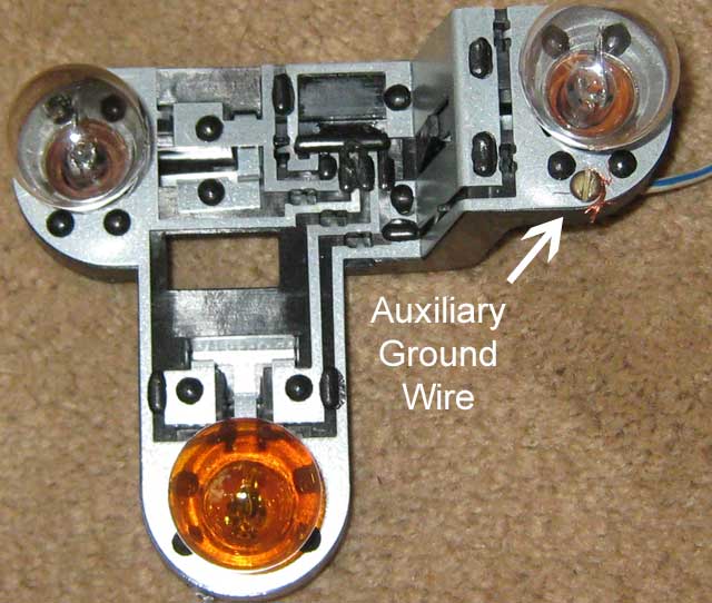
Figure 1. Image from SaabNet. Ignore the auxiliary ground wire but note the common negative around the edge of the assembly.

If you have ever seen a vehicle whose tail lights vary in brightness when the indicators are turned on then you are witnessing a similar phenomena due to poor earth connection.

There are a couple of problems with this approach:

  1. You will find that the main part of lamp holders are metal and connect directly to the chassis and are shared between the tail, brake, reversing and directional indicator lights. Isolating the negative will be a problem.
  2. You will find that you create backfeeds. e.g., If you open the ground connection on all lamps and press the brake pedal you will feed out through the brake lamps to the now floating ground plate of the tail lights, back through the indicator lamps and light up the dashboard indicators and backfeed the flasher unit.

It would be much better to add series switches / relay contacts on each circuit.

If you have ever seen a vehicle whose tail lights vary in brightness when the indicators are turned on then you are witnessing a similar phenomena due to poor earth connection.

There are a couple of problems with this approach:

  1. You will find that the main part of lamp holders are metal and connect directly to the chassis and are shared between the tail, brake, reversing and directional indicator lights. Isolating the negative will be a problem.
  2. You will find that you create backfeeds. e.g., If you open the ground connection on all lamps and press the brake pedal you will feed out through the brake lamps to the now floating ground plate of the tail lights, back through the indicator lamps and light up the dashboard indicators for example. You will also backfeed the flasher unit (but this is unlikely to cause trouble).

It would be much better to add series switches / relay contacts on each circuit.

enter image description here

Figure 1. Image from SaabNet. Ignore the auxiliary ground wire but note the common negative around the edge of the assembly.

If you have ever seen a vehicle whose tail lights vary in brightness when the indicators are turned on then you are witnessing a similar phenomena due to poor earth connection.

Source Link
Transistor
  • 180.3k
  • 14
  • 193
  • 417

There are a couple of problems with this approach:

  1. You will find that the main part of lamp holders are metal and connect directly to the chassis and are shared between the tail, brake, reversing and directional indicator lights. Isolating the negative will be a problem.
  2. You will find that you create backfeeds. e.g., If you open the ground connection on all lamps and press the brake pedal you will feed out through the brake lamps to the now floating ground plate of the tail lights, back through the indicator lamps and light up the dashboard indicators and backfeed the flasher unit.

It would be much better to add series switches / relay contacts on each circuit.

If you have ever seen a vehicle whose tail lights vary in brightness when the indicators are turned on then you are witnessing a similar phenomena due to poor earth connection.