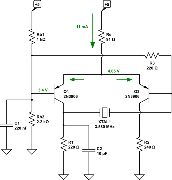
It may be easier to understand if you just start with a long tailed pair -- a differential amplifier. Let me lay it out that way to see if that helps:

simulate this circuit – Schematic created using CircuitLab
I've shown a current and a few voltage values on the schematic. These are roughly true once it starts running. But \$C_1\$ starts out discharged, so those values take a while to reach. At first, \$C_1\$ pulls hard on \$Q_1\$'s base and saturates it, adding current from \$R_e\$ to current from \$R_{b1}\$, in order to charge up \$C_1\$. At some point in this process, and I would guess that it would take about \$\Delta t= \frac{\Delta V\cdot I}{C_1}=\frac{3.4\:\textrm{V}\cdot 15\:\textrm{mA}}{220\:\textrm{nF}}\approx 50\:\mu\textrm{s}\$ before things started rolling, \$Q_1\$ will come out of saturation and things will start to operate more normally. (There's also some diffusion charge storage that was built up into \$Q_1\$, but that's probably only another few added \$\mu\$s. Nothing big.)
As \$Q_1\$ comes out of this initial saturation, it's \$\beta\$ starts to take hold, its base ceases to contribute to charging \$C_1\$, and the voltage drop across \$R_1\$ declines by at least a few tenths of a volt as \$Q_1\$'s \$V_{CE}\$ finally exceeds \$1\:\textrm{V}\$. This drop is passed through the crystal and appears as a slight pull-down at the base of \$Q_2\$, which diverts current through its collector and away from the collector of \$Q_1\$, which causes the drop across \$R_1\$ to decline still further and helps to emphasize this diversion for a moment. However, \$R_3\$ rapidly charges the crystal back up and drives \$Q_2\$'s base back upwards causing it to divert less and allowing \$Q_1\$ to begin diverting more current through its collector, causing the drop across \$R_1\$ to increase again and drive \$Q_2\$'s base further up, as well.
(\$R_{b1}\$ and \$R_{b2}\$ form a Thevenin resistance of about \$680\:\Omega\$. I seem to recall these crystals were about \$100\:\textrm{pF}\$ or so, so working around the loop I see \$680\:\Omega+220\:\Omega+220\:\Omega\$ in series with about \$100\:\textrm{pF}\$ giving about \$110\:\textrm{ns}\$ per half-cycle, which works out to about \$4.5\:\textrm{MHz}\$. So I must be a little wrong about the capacitance of these crystals, I think. The idea is that the natural frequency should be close to the crystal and that the crystal would then "pull it in" tightly.)
Once equilibrium is reached, \$Q_1\$'s base will be very tightly held to its nominal value by \$C_1\$. I think \$C_1\$ is mostly there to set the start-up timing. It probably could be larger still, with the price being that it would take longer to start up. Most of the variation is taking place at \$Q_2\$'s base. Remember that the collector current will vary by a factor of 10 for a \$60\:\textrm{mV}\$ change in \$V_{BE}\$. \$Q_2\$ will be entirely turned off when its base reaches the \$4.05\:\textrm{V}\$ of its emitter. So I expect that to be the highest voltage seen at the base of \$Q_2\$. The lowest voltage there will be approximately that much, less the voltage drop of \$R_1\$ caused by half the current through \$R_e\$, so I think about \$1.2\:\textrm{V}\$ less, or \$2.85\:\textrm{V}\$ at a guess. In short, I expect \$V_{PP}=1.2\:\textrm{V}\$ at \$Q_2\$'s base, centered relatively close to the \$3.4\:\textrm{V}\$ experienced at \$Q_1\$'s base (with perhaps a very tiny relative offset to it.)

