edited body
Source Link
D.A.S.
  • 148k
  • 3
  • 56
  • 190

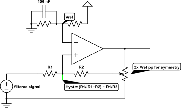
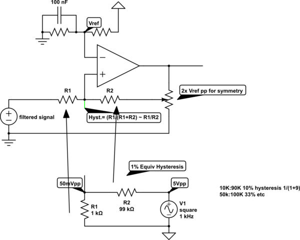
The solution for hysteresis uses the same "design logic" with R ratios as you would for gain with negative feedback except using positive feedback.

  • The key here is to introduce a controlled source impedance and feedback R to give the desired ratio , e.g. 1% 1K source 100k feedback
  • The other key is you need to modify the full scale deflection of the output so that your input signal must be always mid-scale to the full scale output ( attenuated by R ratios if necessary)
schematicschematic

simulate this circuitsimulate this circuit – Schematic created using CircuitLab

  • if the input signal has a poor SNR then it is wise to analyze the "useful" bandwidth of the signal and design a filter to match that spectrum, and notch the noise if possible.
    • e.g. 4th order 5Hz LPF using dual OP Amp and 4 RC values
  • If the noise is "mechanical" then add stiffeners.

Note the LT1720 has 2~7mV hysteresis and your signal has 100 mVpp noise while your thresholds are only 200mVpp apart. So although possible to make a clean toggle, I would reduce the noise 5:1 and increase hysteresis to 20mV

The solution for hysteresis uses the same "design logic" with R ratios as you would for gain with negative feedback except using positive feedback.

  • The key here is to introduce a controlled source impedance and feedback R to give the desired ratio , e.g. 1% 1K source 100k feedback
  • The other key is you need to modify the full scale deflection of the output so that your input signal must be always mid-scale to the full scale output ( attenuated by R ratios if necessary)

schematic

simulate this circuit – Schematic created using CircuitLab

  • if the input signal has a poor SNR then it is wise to analyze the "useful" bandwidth of the signal and design a filter to match that spectrum, and notch the noise if possible.
    • e.g. 4th order 5Hz LPF using dual OP Amp and 4 RC values
  • If the noise is "mechanical" then add stiffeners.

Note the LT1720 has 2~7mV hysteresis and your signal has 100 mVpp noise while your thresholds are only 200mVpp apart. So although possible to make a clean toggle, I would reduce the noise 5:1 and increase hysteresis to 20mV

added 227 characters in body
Source Link
D.A.S.
  • 148k
  • 3
  • 56
  • 190

The solution for hysteresis uses the same "design logic" with R ratios as you would for gain with negative feedback except using positive feedback.

  • The key here is to introduce a controlled source impedance and feedback R to give the desired ratio , e.g. 1% 1K source 100k feedback
  • The other key is you need to modify the full scale deflection of the output so that your input signal must be always mid-scale to the full scale output ( attenuated by R ratios if necessary)

schematic

simulate this circuit – Schematic created using CircuitLab

  • if the input signal has a poor SNR then it is wise to analyze the "useful" bandwidth of the signal and design a filter to match that spectrum, and notch the noise if possible.
    • e.g. 4th order 5Hz LPF using dual OP Amp and 4 RC values
  • If the noise is "mechanical" then add stiffeners.

Note the LT1720 has 2~7mV hysteresis and your signal has 100 mVpp noise while your thresholds are only 200mVpp apart. So although possible to make a clean toggle, I would reduce the noise 5:1 and increase hysteresis to 20mV

The solution for hysteresis uses the same "design logic" with R ratios as you would for gain with negative feedback except using positive feedback.

  • The key here is to introduce a controlled source impedance and feedback R to give the desired ratio , e.g. 1% 1K source 100k feedback
  • The other key is you need to modify the full scale deflection of the output so that your input signal must be always mid-scale to the full scale output ( attenuated by R ratios if necessary)

schematic

simulate this circuit – Schematic created using CircuitLab

  • if the input signal has a poor SNR then it is wise to analyze the "useful" bandwidth of the signal and design a filter to match that spectrum, and notch the noise if possible.
    • e.g. 4th order 5Hz LPF using dual OP Amp and 4 RC values
  • If the noise is "mechanical" then add stiffeners.

Note the LT1720 has 2~7mV hysteresis and your signal has 100 mVpp noise while your thresholds are only 200mVpp apart. So although possible to make a clean toggle, I would reduce the noise 5:1 and increase hysteresis to 20mV

added 68 characters in body
Source Link
D.A.S.
  • 148k
  • 3
  • 56
  • 190

The solution for hysteresis uses the same "design logic" with R ratios as you would for gain with negative feedback except using positive feedback.

  • The key here is to introduce a controlled source impedance and feedback R to give the desired ratio , e.g. 1% 1K source 100k feedback
  • The other key is you need to modify the full scale deflection of the output so that your input signal must be always mid-scale to the full scale output ( attenuated by R ratios if necessary)

schematic

simulate this circuit – Schematic created using CircuitLab

  • if the input signal has a poor SNR then it is wise to analyze the "useful" bandwidth of the signal and design a filter to match that spectrum, and notch the noise if possible. If
    • e.g. 4th order 5Hz LPF using dual OP Amp and 4 RC values
  • If the noise is "mechanical" then add stiffeners.

schematic

simulate this circuit – Schematic created using CircuitLab

The solution for hysteresis uses the same "design logic" with R ratios as you would for gain with negative feedback except using positive feedback.

  • The key here is to introduce a controlled source impedance and feedback R to give the desired ratio , e.g. 1% 1K source 100k feedback
  • The other key is you need to modify the full scale deflection of the output so that your input signal must be always mid-scale to the full scale output ( attenuated by R ratios if necessary)
  • if the input signal has a poor SNR then it is wise to analyze the "useful" bandwidth of the signal and design a filter to match that spectrum, and notch the noise if possible. If the noise is "mechanical" then add stiffeners.

schematic

simulate this circuit – Schematic created using CircuitLab

The solution for hysteresis uses the same "design logic" with R ratios as you would for gain with negative feedback except using positive feedback.

  • The key here is to introduce a controlled source impedance and feedback R to give the desired ratio , e.g. 1% 1K source 100k feedback
  • The other key is you need to modify the full scale deflection of the output so that your input signal must be always mid-scale to the full scale output ( attenuated by R ratios if necessary)

schematic

simulate this circuit – Schematic created using CircuitLab

  • if the input signal has a poor SNR then it is wise to analyze the "useful" bandwidth of the signal and design a filter to match that spectrum, and notch the noise if possible.
    • e.g. 4th order 5Hz LPF using dual OP Amp and 4 RC values
  • If the noise is "mechanical" then add stiffeners.
Source Link
D.A.S.
  • 148k
  • 3
  • 56
  • 190
Loading