The circuit is correct. However it will not work very well in practice with discrete parts- the transistors will be mismatched in Vbe and temperature. It works well on a monolithic chip where the transistors are matched and kept at the same temperature. In simulation those effects do not show up by default.
The current mirror will saturate if (approximately) R2>R1. 28mA*400\$\Omega\$ = 11.2V, leaving only 800mV across Q2+Q3.
Any improvements would depend on what exactly you are trying to accomplish. An LED does not behave like a resistor and this circuit does not really regulate the current to a set number, it just controls it roughly proportional to the input voltage minus a diode drop. A few penny op-amp and a transistor will do a much better job of that.
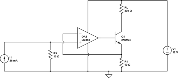
Edit: Example of the above:

simulate this circuit – Schematic created using CircuitLab
You can replace I1 with a resistor from R3 to +12 if you want to make the current proportional to the supply voltage.
