Using summing amplifier you can sum the twoUsing summing amplifier you can sum the two DAC outputs. You can use R1=100k, R2=R3=100 Ohm. This way the output will be Vout = -(V1 + V2 / 1000). You'll need dual supply and if you want it non-inverted you need to put another inverting amplifier with gain = 1.
So let's say you have 12 bit DAC with 2 outputs and reference 4.096V. Then (if you have second inverting amplifier) one increment from DAC 1 will increase output with 1uV, and one increment from DAC 2 will increase the output with 1mV. That's not 24 bit in total. It's about 22 bits. In theory you you can choose R1 to be 4096 times bigger than R2 and R3 and get 24 bits, but You won't get better results. You'll have a lot of noise problems in microvolts range even if you pick a good low noise opamp.
Update
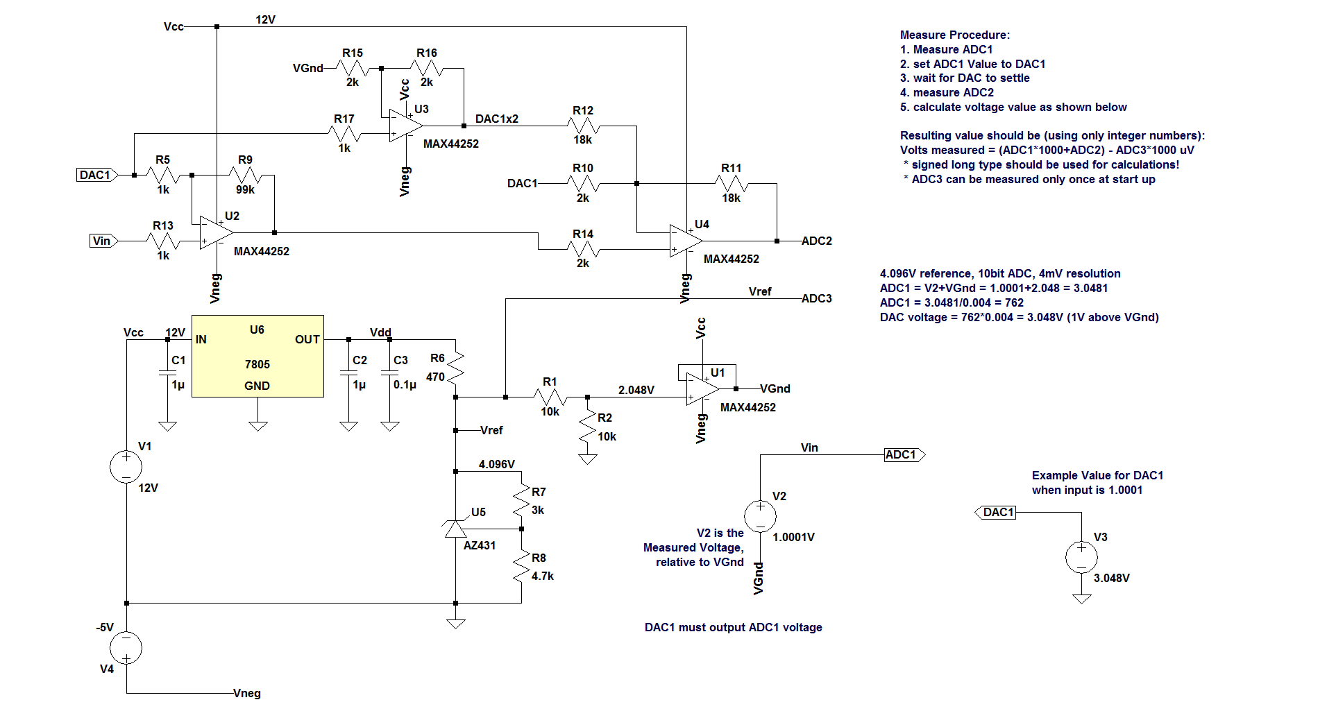
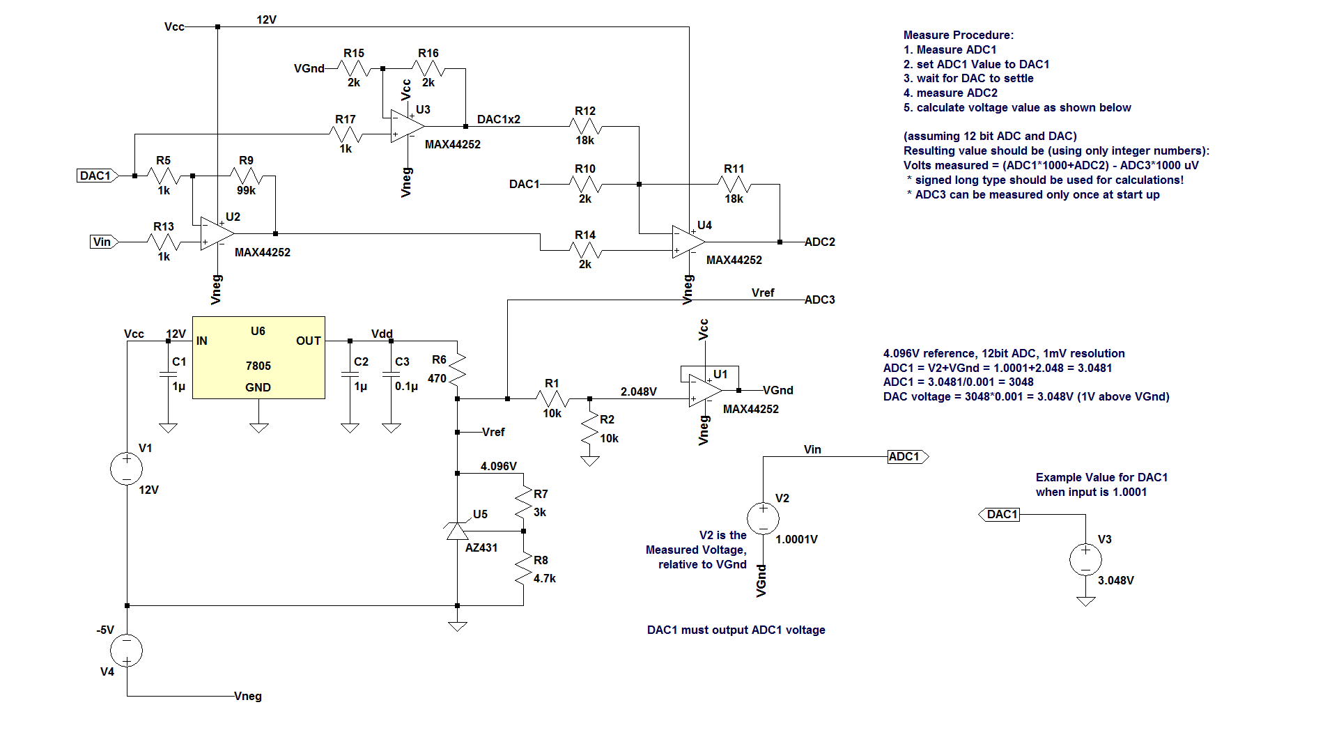
I though it's a question about DAC outputsbecause I was searching for DACs. You Here is how you apply similar principle with ADCs. Instead of summing you have to subtract ADC1 result then multiply by 1000 before measure with ADC2.

Instead of AZ431 you can use R1=100kany other 2.5V reference or another adjustable reference with proper passives to get exactly 4.096V. The less temperature drift the reference has, R2=R3=100 Ohmthe better the results. This wayAlso it has to be low noise. Note that as is it's probably not accurate enough. It'll be nice to put 500 ohm multi turn trimpot between R7 and R8 with wiper to the outputreference input and tweak it for Vref = 4.096V exactly. Also a trimpot(2) will be Vout =needed between R1 and R2 with wiper to U1 positive input. Tweak it for 2.048V on VGnd. U1 is just any low noise opamp. (BTW AZ431 is awful for the job. I put it because I had the symbol).
It's very critical for U2, U3 and U4 to be zero offset chopper amps. U2 is more important because it multiplies by 100. every 1 microvolt gets to 100 microvolts. If you use OP07 and you zero it properly and the temperature changes with 10 degrees then you get 13 uV offset which translates to 1.3 mV on the output of U4. That's 13 mV in ADC output which makes ADC2 almost useless.
Also U3 must be able to reach 6.048V - that's VGnd(V12.048V) + V22xVinmax / 1000(2x2V=4V). You'll need dualThat's the whole idea of having Vcc = +12V power supply. Vcc can be as low as 6.5V when MAX44252 is used. Since MAX44252 is rail to rail opamp negative supply can be skipped and if you want it nonVss of the opamp can be connected to ground. That's true for any opamp that can go as low as 48mV on it's output.
MAX44252 has 2-inverted you need4uV offset voltage (typical) and 1 to put another inverting amplifier with gain =5 nV temperature drift. It's $2.64 on digikey in quantities of 1 and it's quadopamp so only one chip will do the job.
So let's say youHow it works? Let's have 12 bit10bit DAC with 2 outputs and referencefor example. Resolution is 4.096V096/1024 = 4mV. Input signal must be relative to VGnd, which is half of Vref. ADC1 measures input voltage as normal. Then outputs the value via DAC1. The difference between Vin and DAC1 is the error that you need to amplify, measure and add to the ADC1 result. U2 amplifies the difference Vin - DAC1, relative to DAC1, with gain of 100. U4 amplifies that difference by 10 and also subtracts DAC1, relative to VGnd. That makes ADC2 = (ifVin - DAC1) * 1000, relative to VGnd. In other words if you have second inverting amplifier) one increment from DAC 1 will increase output with 1uV.234567V on Vin, relative to VGnd. ADC1 will measure value of 821 because resolution is 4mV and one increment from(2.048+1.234567)/0.004 = 820.64175. So the DAC 2value will increase the output with 1mVbe set to 309 which is 3090.004V = 1.236V. Now ADC2 will get 1.234567-1.236=-0.0014331000 = -1.433V relative to VGnd (ideally). That's 2.048-1.433=0.615V common mode. 0.615V / 0.004 = 153.75. So notADC2 value = 154 24 bit in total. It's about 22 bitseasier to calculate value in microvolts to avoid using float. In theory you you can choose R1 to be 4096 times bigger than R2 and R3 and get 24 bits, but You won'tconvert ADC2 in mV we have to multipy the value by 4: VADC1 = 8214 = 3284mV. To convert to uV we need to multiply by 1000. Or that's ADC1 value multiplied by 4000. 8214000 = 3284000. So ADC1 voltage with respect to VGnd is 3284000-2048000 = 1236000uV. The ADC2 is already multiplied by 1000 so we need to multiply only by 4: VADC2 = 154*4 = 616. To get better resultsvoltage relative to VGnd we need to subtract VGnd: 616-2048 = -1432uV. You'llWe take VGnd = 2048uV here because we have a lotx1000 amplification.Now we add VADC1 and VADC2: 1236000 + (-1432) = 1234568uV or 1.234568V
Of course that's just dreams because when you deal with microvolts there will be all kinds of noisehorrible problems in microvolts range even- opamp noise, resistors noise, voltage offset, temperature drift, gain error ... But if you pick ause decent parts, at least 1% resistors and you programmatically null the offset and correct the gain you might get reasonably good low noise opampresult. Of course you can't expect to see stable input to the last digit. maybe you can limit the resolution to 10uV (divide the result by 10). Also the multiply by 4 can be done by summing 4 sequential results to have some averaging.
OnKeep in mind that nothing of this is tested. I simulated only the second invertingamplifier stage without taking into account noise and opamp you can put low pass filteroffset. If someone decides to reducebuild it write the noiseresults in the comments.


