added 299 characters in body
Source Link
hkBattousai
  • 14.2k
  • 35
  • 116
  • 201

I have an experimental circuit like below:
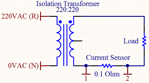
Experimental Circuit

My aim is to measure maximum or effective value the current on the load.
The current sensor is a simple \$ 0.1 \Omega \$, \$5W\$ resistor.

I filtered the voltage on the current sensor with the following cascaded RC filter:
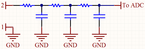
3rd Order Passive RC Filter

The output of the filter show no signal (\$0V\$). This was an expected result since I was applying a sinusoidal signal to filter like this.

I can't use a diode at the filter stage since the voltage on the current sensor is at the level of millivolts.

Is there any simple trick for reading the voltage on the current sensor? If possible, I don't want to change the main structure of this circuit too much.


EDIT:

How about this alternative circuit?
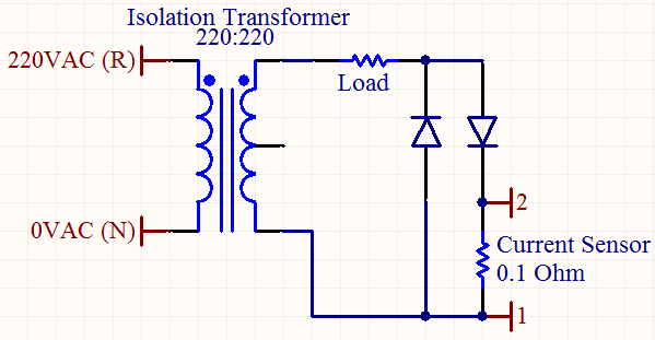
Alternative Circuit

Assuming that both alternances of the AC signal have the same shape on load, I can calculate the current on the load by only considering the positive alternance.


Notes:

  1. AC frequency is 50Hz.
  2. I'm using the transformer to protect my oscilloscope.
  3. At the filter stage, all resistors and capacitor have the same values (\$R=100k \Omega , C=1 \mu F\$).
  4. The ADC is on a microcontroller (maybe I can add an opamp beforehand for scaling), so I can do any algebraic manipulations on the sensed value.
  5. The load is generic. I want it to be as wide range as possible. I'm using a \$60W\$ lamp for this experiment.

I have an experimental circuit like below:

Experimental Circuit

My aim is to measure maximum or effective value the current on the load.
The current sensor is a simple \$ 0.1 \Omega \$, \$5W\$ resistor.

I filtered the voltage on the current sensor with the following cascaded RC filter:
3rd Order Passive RC Filter

The output of the filter show no signal (\$0V\$). This was an expected result since I was applying a sinusoidal signal to filter like this.

I can't use a diode at the filter stage since the voltage on the current sensor is at the level of millivolts.

Is there any simple trick for reading the voltage on the current sensor? If possible, I don't want to change the main structure of this circuit too much.


EDIT:

How about this alternative circuit?

Alternative Circuit

Assuming that both alternances of the AC signal have the same shape on load, I can calculate the current on the load by only considering the positive alternance.


Notes:

  1. AC frequency is 50Hz.
  2. I'm using the transformer to protect my oscilloscope.
  3. At the filter stage, all resistors and capacitor have the same values (\$R=100k \Omega , C=1 \mu F\$).
  4. The ADC is on a microcontroller (maybe I can add an opamp beforehand for scaling), so I can do any algebraic manipulations on the sensed value.
  5. The load is generic. I want it to be as wide range as possible. I'm using a \$60W\$ lamp for this experiment.
Tweeted twitter.com/#!/StackElectronix/status/187462354513039360
removed sreaming boldface
Source Link
stevenvh
  • 146.6k
  • 21
  • 460
  • 669

I have an experimental circuit like below:

Experimental Circuit

My aim is to measure maximum or effective value the current on the load.
The current sensor is a simple \$ 0.1 \Omega \$, \$5W\$ resistor.
My aim is to measure maximum or effective value the current on the load.
The current sensor is a simple \$ 0.1 \Omega \$, \$5W\$ resistor.

I filtered the voltage on the current sensor with the following cascaded RC filter: I filtered the voltage on the current sensor with the following cascaded RC filter:
3rd Order Passive RC Filter

The output of the filter show no signal (\$0V\$). This was an expected result since I was applying a sinusoidal signal to filter like this. The output of the filter show no signal (\$0V\$). This was an expected result since I was applying a sinusoidal signal to filter like this.

I can't use a diode at the filter stage since the voltage on the current sensor is at the level of millivolts. I can't use a diode at the filter stage since the voltage on the current sensor is at the level of millivolts.

Is there any simple trick for reading the voltage on the current sensor? If possible, I don't want to change the main structure of this circuit too much. Is there any simple trick for reading the voltage on the current sensor? If possible, I don't want to change the main structure of this circuit too much.


Notes:

  1. AC frequency is 50Hz.
  2. I'm using the transformer to protect my oscilloscope.
  3. At the filter stage, all resistors and capacitor have the same values (\$R=100k \Omega , C=1 \mu F\$).
  4. The ADC is on a microcontroller (maybe I can add an opamp beforehand for scaling), so I can do any algebraic manipulations on the sensed value.
  5. The load is generic. I want it to be as wide range as possible. I'm using a \$60W\$ lamp for this experiment.

I have an experimental circuit like below:
Experimental Circuit

My aim is to measure maximum or effective value the current on the load.
The current sensor is a simple \$ 0.1 \Omega \$, \$5W\$ resistor.

I filtered the voltage on the current sensor with the following cascaded RC filter:
3rd Order Passive RC Filter

The output of the filter show no signal (\$0V\$). This was an expected result since I was applying a sinusoidal signal to filter like this.

I can't use a diode at the filter stage since the voltage on the current sensor is at the level of millivolts.

Is there any simple trick for reading the voltage on the current sensor? If possible, I don't want to change the main structure of this circuit too much.

Notes:

  1. AC frequency is 50Hz.
  2. I'm using the transformer to protect my oscilloscope.
  3. At the filter stage, all resistors and capacitor have the same values (\$R=100k \Omega , C=1 \mu F\$).
  4. The ADC is on a microcontroller (maybe I can add an opamp beforehand for scaling), so I can do any algebraic manipulations on the sensed value.
  5. The load is generic. I want it to be as wide range as possible. I'm using a \$60W\$ lamp for this experiment.

I have an experimental circuit like below:

Experimental Circuit

My aim is to measure maximum or effective value the current on the load.
The current sensor is a simple \$ 0.1 \Omega \$, \$5W\$ resistor.

I filtered the voltage on the current sensor with the following cascaded RC filter:
3rd Order Passive RC Filter

The output of the filter show no signal (\$0V\$). This was an expected result since I was applying a sinusoidal signal to filter like this.

I can't use a diode at the filter stage since the voltage on the current sensor is at the level of millivolts.

Is there any simple trick for reading the voltage on the current sensor? If possible, I don't want to change the main structure of this circuit too much.


Notes:

  1. AC frequency is 50Hz.
  2. I'm using the transformer to protect my oscilloscope.
  3. At the filter stage, all resistors and capacitor have the same values (\$R=100k \Omega , C=1 \mu F\$).
  4. The ADC is on a microcontroller (maybe I can add an opamp beforehand for scaling), so I can do any algebraic manipulations on the sensed value.
  5. The load is generic. I want it to be as wide range as possible. I'm using a \$60W\$ lamp for this experiment.
Source Link
hkBattousai
  • 14.2k
  • 35
  • 116
  • 201

How do I sense sinusoidal voltage/current on a resistor?

I have an experimental circuit like below:
Experimental Circuit

My aim is to measure maximum or effective value the current on the load.
The current sensor is a simple \$ 0.1 \Omega \$, \$5W\$ resistor.

I filtered the voltage on the current sensor with the following cascaded RC filter:
3rd Order Passive RC Filter

The output of the filter show no signal (\$0V\$). This was an expected result since I was applying a sinusoidal signal to filter like this.

I can't use a diode at the filter stage since the voltage on the current sensor is at the level of millivolts.

Is there any simple trick for reading the voltage on the current sensor? If possible, I don't want to change the main structure of this circuit too much.

Notes:

  1. AC frequency is 50Hz.
  2. I'm using the transformer to protect my oscilloscope.
  3. At the filter stage, all resistors and capacitor have the same values (\$R=100k \Omega , C=1 \mu F\$).
  4. The ADC is on a microcontroller (maybe I can add an opamp beforehand for scaling), so I can do any algebraic manipulations on the sensed value.
  5. The load is generic. I want it to be as wide range as possible. I'm using a \$60W\$ lamp for this experiment.