Tweeted twitter.com/StackElectronix/status/843515449660850181
added 118 characters in body
Source Link
RS System
  • 179
  • 4
  • 13

Charging lithium battery while at the same time trying to use circuit didn’t quite workout, with problems like the circuit not turning on and the battery never finish charging.

The battery is 3.7V and capacity of 300mAH.

However I found the microchip app note on same issue.

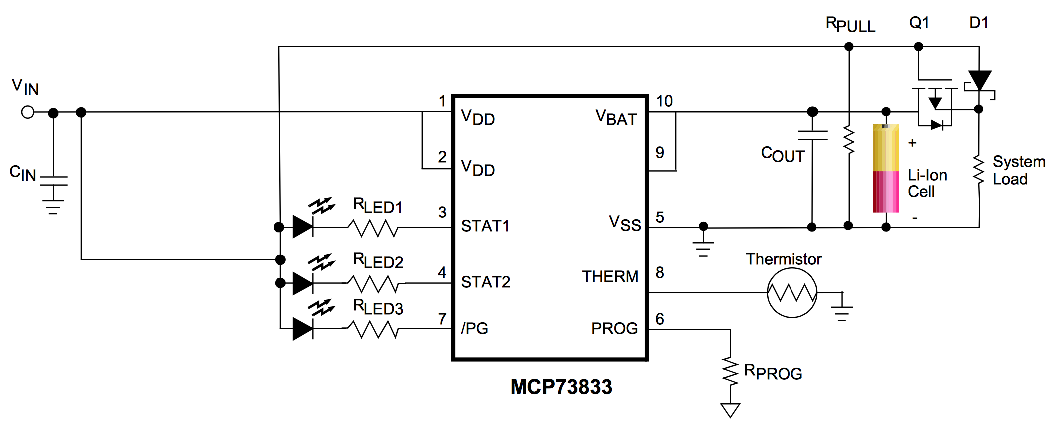
Here is circuit:-enter image description here

When USB power is applied at Vin this circuit will turn off Q1, and then the load will instead use power from USB through D1. This allows the battery to charge normally without any outside disturbances.

  • The Q1 is P channel MOSFET, but I am not able to understand the connection. Why source is connected to load and Drain connected to Vbat? It should be reverse.

  • Which MOSFET should I select for this circuit? If my Load Current is 100mA max? What should be the Rd (on) and VGS(th) of the MOSFET which I can use in above circuit? Any suggestion for the part number

I am considering this P-Channel MOSFET DMP1045U http://in.element14.com/diodes-inc/dmp1045u/mosfet-p-ch-w-esd-12v-sot23/dp/2061526

I am considering Diode B130LAW :- http://www.farnell.com/datasheets/887879.pdf?_ga=1.83230549.251839788.1488841003

Also D1 is to prevent current flowing from the battery into the charging power source. D1 should be a schottky diode. The reverse leakage current of D1, which could be up to a few hundred microamp (schottky diodes are very leaky).

  • This leakage current will create a small voltage at the MOSFET gate which, if high enough, could cause the MOSFET to not turn back on properly when the main Vin power is removed. How to overcome this?

  • How to minimise the leakage current of D1?

  • What should be the Value of Rpull ?

Charging lithium battery while at the same time trying to use circuit didn’t quite workout, with problems like the circuit not turning on and the battery never finish charging.

The battery is 3.7V and capacity of 300mAH.

However I found the microchip app note on same issue.

Here is circuit:-enter image description here

When USB power is applied at Vin this circuit will turn off Q1, and then the load will instead use power from USB through D1. This allows the battery to charge normally without any outside disturbances.

  • The Q1 is P channel MOSFET, but I am not able to understand the connection. Why source is connected to load and Drain connected to Vbat? It should be reverse.

  • Which MOSFET should I select for this circuit? If my Load Current is 100mA max? What should be the Rd (on) and VGS(th) of the MOSFET which I can use in above circuit? Any suggestion for the part number

I am considering this P-Channel MOSFET DMP1045U http://in.element14.com/diodes-inc/dmp1045u/mosfet-p-ch-w-esd-12v-sot23/dp/2061526

I am considering Diode B130LAW :- http://www.farnell.com/datasheets/887879.pdf?_ga=1.83230549.251839788.1488841003

Also D1 is to prevent current flowing from the battery into the charging power source. D1 should be a schottky diode. The reverse leakage current of D1, which could be up to a few hundred microamp (schottky diodes are very leaky).

  • This leakage current will create a small voltage at the MOSFET gate which, if high enough, could cause the MOSFET to not turn back on properly when the main Vin power is removed. How to overcome this?

  • How to minimise the leakage current of D1?

  • What should be the Value of Rpull ?

deleted 24 characters in body
Source Link
RS System
  • 179
  • 4
  • 13

Charging lithium battery while at the same time trying to use circuit didn’t quite workout, with problems like the circuit not turning on and the battery never finish charging.

The battery is 3.7V and capacity of 300mAH.

However I found the microchip app note on same issue.

Here is circuit:-enter image description here

When USB power is applied at Vin this circuit will turn off Q1, and as long as(Vin – D1 VF) is above (Vbat – Q1 VSD) then the load will instead use power from USB through D1. This allows the battery to charge normally without any outside disturbances.

The Q1 is P channel MOSFET, but I am not able to understand the connection. Why source is connected to load and Drain connected to Vbat? It should be reverse.

Which MOSFET should I select for this circuit, if Vin is +5v(+/-0.25) and Vbat is +4.2V - 3.2V what should be Rdon and Vgs(th) for this MOSFET. How to calculate above parameters?

  • The Q1 is P channel MOSFET, but I am not able to understand the connection. Why source is connected to load and Drain connected to Vbat? It should be reverse.

  • Which MOSFET should I select for this circuit? If my Load Current is 100mA max? What should be the Rd (on) and VGS(th) of the MOSFET which I can use in above circuit? Any suggestion for the part number

I am considering this P-Channel MOSFET DMP1045U http://in.element14.com/diodes-inc/dmp1045u/mosfet-p-ch-w-esd-12v-sot23/dp/2061526

Also D1 is to prevent current flowing from the battery into the charging power source. D1 should be a schottky diode. reverseThe reverse leakage current of D1, which could be up to a few hundred microamp (schottky diodes are very leaky). This leakage current will create a small voltage at the MOSFET gate which, if high enough, could cause the MOSFET to not turn back on properly when the main Vin power is removed. How to overcome this?

How to minimise the leakage current of D1, in the range of 1-10uA(or may be less). Any reference part?

  • This leakage current will create a small voltage at the MOSFET gate which, if high enough, could cause the MOSFET to not turn back on properly when the main Vin power is removed. How to overcome this?

  • How to minimise the leakage current of D1?

  • What should be the Value of Rpull ?

Charging lithium battery while at the same time trying to use circuit didn’t quite workout, with problems like the circuit not turning on and the battery never finish charging.

The battery is 3.7V and capacity of 300mAH.

However I found the microchip app note on same issue.

Here is circuit:-enter image description here

When USB power is applied at Vin this circuit will turn off Q1, and as long as(Vin – D1 VF) is above (Vbat – Q1 VSD) then the load will instead use power from USB through D1. This allows the battery to charge normally without any outside disturbances.

The Q1 is P channel MOSFET, but I am not able to understand the connection. Why source is connected to load and Drain connected to Vbat? It should be reverse.

Which MOSFET should I select for this circuit, if Vin is +5v(+/-0.25) and Vbat is +4.2V - 3.2V what should be Rdon and Vgs(th) for this MOSFET. How to calculate above parameters?

I am considering this P-Channel MOSFET DMP1045U http://in.element14.com/diodes-inc/dmp1045u/mosfet-p-ch-w-esd-12v-sot23/dp/2061526

Also D1 is to prevent current flowing from the battery into the charging power source. D1 should be a schottky diode. reverse leakage current of D1, which could be up to a few hundred microamp (schottky diodes are very leaky). This leakage current will create a small voltage at the MOSFET gate which, if high enough, could cause the MOSFET to not turn back on properly when the main Vin power is removed. How to overcome this?

How to minimise the leakage current of D1, in the range of 1-10uA(or may be less). Any reference part?

Charging lithium battery while at the same time trying to use circuit didn’t quite workout, with problems like the circuit not turning on and the battery never finish charging.

The battery is 3.7V and capacity of 300mAH.

However I found the microchip app note on same issue.

Here is circuit:-enter image description here

When USB power is applied at Vin this circuit will turn off Q1, and then the load will instead use power from USB through D1. This allows the battery to charge normally without any outside disturbances.

  • The Q1 is P channel MOSFET, but I am not able to understand the connection. Why source is connected to load and Drain connected to Vbat? It should be reverse.

  • Which MOSFET should I select for this circuit? If my Load Current is 100mA max? What should be the Rd (on) and VGS(th) of the MOSFET which I can use in above circuit? Any suggestion for the part number

I am considering this P-Channel MOSFET DMP1045U http://in.element14.com/diodes-inc/dmp1045u/mosfet-p-ch-w-esd-12v-sot23/dp/2061526

Also D1 is to prevent current flowing from the battery into the charging power source. D1 should be a schottky diode. The reverse leakage current of D1, which could be up to a few hundred microamp (schottky diodes are very leaky).

  • This leakage current will create a small voltage at the MOSFET gate which, if high enough, could cause the MOSFET to not turn back on properly when the main Vin power is removed. How to overcome this?

  • How to minimise the leakage current of D1?

  • What should be the Value of Rpull ?

added 136 characters in body
Source Link
RS System
  • 179
  • 4
  • 13

Charging lithium battery while at the same time trying to use circuit didn’t quite workout, with problems like the circuit not turning on and the battery never finish charging.

The battery is 3.7V and capacity of 300mAH.

However I found the microchip app note on same issue.

Here is circuit:-enter image description here

When USB power is applied at Vin this circuit will turn off Q1, and as long as(Vin – D1 VF) is above (Vbat – Q1 VSD) then the load will instead use power from USB through D1. This allows the battery to charge normally without any outside disturbances.

The Q1 is P channel MOSFET, but I am not able to understand the connection. Why source is connected to load and Drain connected to Vbat? It should be reverse.

Which MOSFET should I select for this circuit, if Vin is +5v(+/-0.25) and Vbat is +4.2V - 3.2V what should be Rdon and Vgs(th) for this MOSFET. How to calculate above parameters?

I am considering this P-Channel MOSFET DMP1045U http://in.element14.com/diodes-inc/dmp1045u/mosfet-p-ch-w-esd-12v-sot23/dp/2061526

Also D1 is to prevent current flowing from the battery into the charging power source. D1 should be a schottky diode. reverse leakage current of D1, which could be up to a few hundred microamp (schottky diodes are very leaky). This leakage current will create a small voltage at the MOSFET gate which, if high enough, could cause the MOSFET to not turn back on properly when the main Vin power is removed. How to overcome this?

How to minimise the leakage current of D1, in the range of 1-10uA(or may be less). Any reference part?

Charging lithium battery while at the same time trying to use circuit didn’t quite workout, with problems like the circuit not turning on and the battery never finish charging.

The battery is 3.7V and capacity of 300mAH.

However I found the microchip app note on same issue.

Here is circuit:-enter image description here

When USB power is applied at Vin this circuit will turn off Q1, and as long as(Vin – D1 VF) is above (Vbat – Q1 VSD) then the load will instead use power from USB through D1. This allows the battery to charge normally without any outside disturbances.

The Q1 is P channel MOSFET, but I am not able to understand the connection. Why source is connected to load and Drain connected to Vbat? It should be reverse.

Which MOSFET should I select for this circuit, if Vin is +5v(+/-0.25) and Vbat is +4.2V - 3.2V what should be Rdon and Vgs(th) for this MOSFET. How to calculate above parameters?

I am considering this P-Channel MOSFET DMP1045U http://in.element14.com/diodes-inc/dmp1045u/mosfet-p-ch-w-esd-12v-sot23/dp/2061526

Also D1 is to prevent current flowing from the battery into the charging power source. D1 should be a schottky diode. reverse leakage current of D1, which could be up to a few hundred microamp (schottky diodes are very leaky). This leakage current will create a small voltage at the MOSFET gate which, if high enough, could cause the MOSFET to not turn back on properly when the main Vin power is removed. How to overcome this?

How to minimise the leakage current of D1, in the range of 1-10uA(or may be less). Any reference part?

deleted 7 characters in body
Source Link
RS System
  • 179
  • 4
  • 13
Loading
Source Link
RS System
  • 179
  • 4
  • 13
Loading