Reworked answer to reflect comments and simulation
Source Link
StainlessSteelRat
  • 8.2k
  • 2
  • 19
  • 34

Alternator Simulation Completely revised answer...

Alternator Simulation

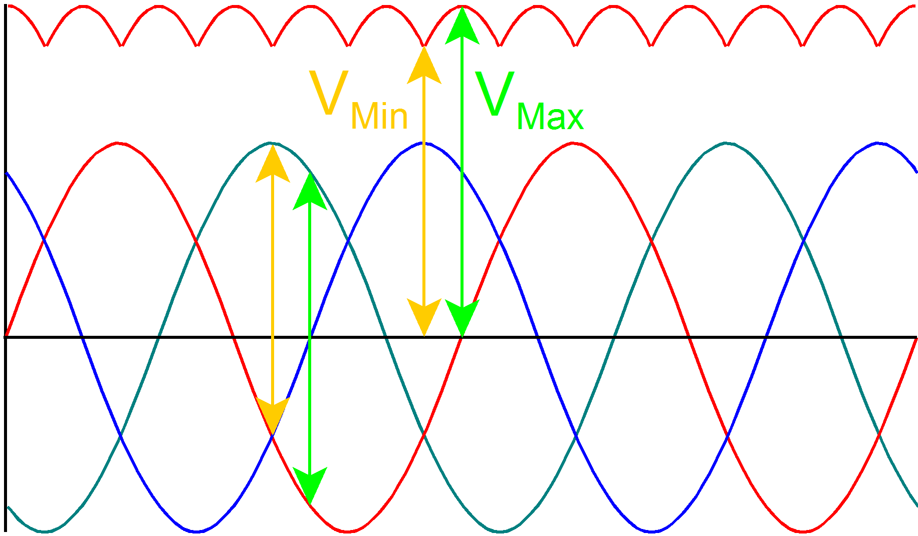
If the alternator produces 9V peak sine waves. Your Red Dot to Green Dot voltage will vary from -9V to 9V.

\$V_{Red} = 9 sin (\omega t) V \$

\$V_{Green} = 9 sin (\omega t\ -\ 120^{\circ}) V \$

\$V_{Blue} = 9 sin (\omega t\ +\ 120^{\circ}) V \$

$$V_{Min} = 9 sin (90^{\circ}) - 9 sin (90^{\circ} +\ 120^{\circ}) - 2 \times 0.7V = 12.1V$$

$$V_{Max} = 9 sin (120^{\circ}) - 9 sin (120^{\circ} +\ 120^{\circ}) - 2 \times 0.7V = 14.19V$$

Alternator OutputAlternator Outputs

The actual voltage seen by the battery will be line-to-line voltage across two phases minus the diode voltages.

We can determine this by looking at two points. Between \$60^{\circ}\$ and \$120^{\circ}\$, we can assume diodes associated with red and blue are conducting\$V_{Line} = \sqrt {3}\ V_{Phase} = \sqrt {3} \times 9V = 15.59V\$.

So at \$90^{\circ} \$, red and blue are conducting. Assuming 0.7V for diodes\$V_{Bat} = V_{Line} - V_{diodes} = 15.59V - 1.4V = 14.19V\$.

$$V_{Min} = V_{Red} - V_{Blue} - 2 V_{Diodes}$$ $$V_{Min} = 9 sin (90^{\circ}) - 9 sin (90^{\circ} +\ 120^{\circ}) - 2 \times 0.7V$$ $$V_{Min} = 9V - (-4.5V) - 2 \times 0.7V = 12.1V$$

At \$120^{\circ}\$, red and blue are conducting. Green is 0\$I_{Bat} = \frac {V_{Bat}} {R} = \frac {14.19V} {100\Omega} = 141.9mA\$.

$$V_{Max} = V_{Red} - V_{Blue} - 2 V_{Diodes}$$ Maximum Power at Resistor: $$V_{Max} = 9 sin (120^{\circ}) - 9 sin (120^{\circ} +\ 120^{\circ}) - 2 \times 0.7V$$$$ P = \frac {V_{Bat}^2}{R} = \frac {(14.19V)^2}{100\Omega} = 2.01W $$ $$V_{Max} = 7.79V - (-7.79V) - 2 \times 0.7V = 14.18V$$


WhichThree-phase Power: $$ P = \sqrt {3}\ V_{Bat}\ I_{Line}\ cos \theta = \sqrt {3} \times 14.19V \times 141.9mA \times 1 = 3.487W$$ The Three-phase Power calculation is \$V_{Line} = \sqrt {3}\ V_{Phase} = \sqrt {3} \times 9V = 15.59V\$, minuswrong because of the 1.4V foraction of the diodes.


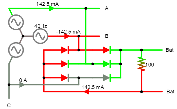
So depending Only two sets are on at the maximum and minimum you see acrosssame time as shown by the battery terminal and blue dot, you shoulddrawing. This also means there will be able to work backwards to derive instantaneous waveforms for alternatorcurrent flowing in the neutral. Your red and green dots Three-Phase Alternator Simulation Circuit Single-phase Power with Line voltages: $$ P = V_{Bat}\ I_{Line}\ cos \theta = 14.19V \times 141.9mA \times 1 = 2.01W$$ This agrees with the load calculation.
At \$90^{\circ}\$Single-phase Power with Phase voltages: $$ P = \sqrt {3}\ V_{Phase}\ I_{Phase}\ cos \theta = \sqrt {3} \times (9V - 0.7V) \times 141.9mA \times 1 = 2.04W$$ Again, \$V_{Blue} = 50\% \ of \ V_{Red}\$ or atthis agrees. Because of the \$120^{\circ}\$\$\sqrt {3} \$, \$V_{Blue} = V_{Red}\$I'd go with line voltages.

Actual voltage will also depend on speed of rotationThe action of alternatorthe diodes also means the Green and Blue dots will NOT be at the same potential.


It's a Image shows +Bat varying from 8.35V to 3.86V, while -phase alternatorBat varies from -3.86V to -8.35V. This brings us back to the \$V_{Min}\$ calculation.

$$P_T = \sqrt {3} V_{Line} I_{Line} cos \theta $$ $$P_T = 3 V_{Phase} I_{Phase} cos \theta $$Battery voltages
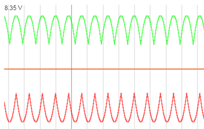
Turned into a dc battery charging circuit.$$V_{Min} = 8.35V - (-3.86V) = 12.21V $$

$$P_T = V_{Alternator} I_{Line}$$$$V_{Min} = 9 sin (90^{\circ}) - 9 sin (90^{\circ} +\ 120^{\circ}) - 2 \times 0.7V = 12.1V$$


TheYour Green and Blue dots shouldDot will be at 0V and the same potentialBlue Dot to Green Dot voltage will vary from -3.86V to -8.35V.

Then measure ALL 3 phase voltages at the same time. If they are all the same, then the Green and Blue dots are at the same potential.Minimum Power: $$ P = \frac {V_{Bat}^2}{R} = \frac {(12.1V)^2}{100\Omega} = 1.46W $$

You say they are NOT, but you provide no evidence. No measurements. No info on alternator. You say ignore this. It is not important. This (should be) a 3\$ \phi\$ alternator connected in wye with two diodes. It is fairly simple. The math is correct and the simulation gives close results. We cannot see what you see and you give us nothingNumbers should scale to work withreal world.


You have not been forthcoming with information, so this is my last on this. Have a nice day....To calculate phase voltage:

  • Measure \$V_{Bat_{Min}}\$.
  • Calculate \$V_{Phase} = (V_{Bat_{Min}}\ +\ 1.4V) \times \frac {2}{3}\$.

To calculate power (Max or Min):

  • Measure \$V_{Bat_{Min}}\$.
  • Measure \$I_{Bat_{Min}}\$.
  • \$P = V_{Bat_{Min}} \ I_{Bat_{Min}}\$
  • Repeat using Max quantities.

Alternator Simulation

If the alternator produces 9V peak sine waves.

\$V_{Red} = 9 sin (\omega t) V \$

\$V_{Green} = 9 sin (\omega t\ -\ 120^{\circ}) V \$

\$V_{Blue} = 9 sin (\omega t\ +\ 120^{\circ}) V \$

Alternator Output

The actual voltage seen by the battery will be line-to-line voltage across two phases minus the diode voltages.

We can determine this by looking at two points. Between \$60^{\circ}\$ and \$120^{\circ}\$, we can assume diodes associated with red and blue are conducting.

So at \$90^{\circ} \$, red and blue are conducting. Assuming 0.7V for diodes.

$$V_{Min} = V_{Red} - V_{Blue} - 2 V_{Diodes}$$ $$V_{Min} = 9 sin (90^{\circ}) - 9 sin (90^{\circ} +\ 120^{\circ}) - 2 \times 0.7V$$ $$V_{Min} = 9V - (-4.5V) - 2 \times 0.7V = 12.1V$$

At \$120^{\circ}\$, red and blue are conducting. Green is 0.

$$V_{Max} = V_{Red} - V_{Blue} - 2 V_{Diodes}$$ $$V_{Max} = 9 sin (120^{\circ}) - 9 sin (120^{\circ} +\ 120^{\circ}) - 2 \times 0.7V$$ $$V_{Max} = 7.79V - (-7.79V) - 2 \times 0.7V = 14.18V$$


Which is \$V_{Line} = \sqrt {3}\ V_{Phase} = \sqrt {3} \times 9V = 15.59V\$, minus the 1.4V for diodes.


So depending on the maximum and minimum you see across the battery terminal and blue dot, you should be able to work backwards to derive instantaneous waveforms for alternator. Your red and green dots.

At \$90^{\circ}\$, \$V_{Blue} = 50\% \ of \ V_{Red}\$ or at \$120^{\circ}\$, \$V_{Blue} = V_{Red}\$.

Actual voltage will also depend on speed of rotation of alternator.


It's a 3-phase alternator.

$$P_T = \sqrt {3} V_{Line} I_{Line} cos \theta $$ $$P_T = 3 V_{Phase} I_{Phase} cos \theta $$

Turned into a dc battery charging circuit.

$$P_T = V_{Alternator} I_{Line}$$


The Green and Blue dots should be at the same potential.

Then measure ALL 3 phase voltages at the same time. If they are all the same, then the Green and Blue dots are at the same potential.

You say they are NOT, but you provide no evidence. No measurements. No info on alternator. You say ignore this. It is not important. This (should be) a 3\$ \phi\$ alternator connected in wye with two diodes. It is fairly simple. The math is correct and the simulation gives close results. We cannot see what you see and you give us nothing to work with.

You have not been forthcoming with information, so this is my last on this. Have a nice day....

Completely revised answer...

Alternator Simulation

If the alternator produces 9V peak sine waves. Your Red Dot to Green Dot voltage will vary from -9V to 9V.

\$V_{Red} = 9 sin (\omega t) V \$

\$V_{Green} = 9 sin (\omega t\ -\ 120^{\circ}) V \$

\$V_{Blue} = 9 sin (\omega t\ +\ 120^{\circ}) V \$

$$V_{Min} = 9 sin (90^{\circ}) - 9 sin (90^{\circ} +\ 120^{\circ}) - 2 \times 0.7V = 12.1V$$

$$V_{Max} = 9 sin (120^{\circ}) - 9 sin (120^{\circ} +\ 120^{\circ}) - 2 \times 0.7V = 14.19V$$

Alternator Outputs

The actual voltage seen by the battery will be line-to-line voltage across two phases minus the diode voltages.

\$V_{Line} = \sqrt {3}\ V_{Phase} = \sqrt {3} \times 9V = 15.59V\$.

\$V_{Bat} = V_{Line} - V_{diodes} = 15.59V - 1.4V = 14.19V\$.

\$I_{Bat} = \frac {V_{Bat}} {R} = \frac {14.19V} {100\Omega} = 141.9mA\$.

Maximum Power at Resistor: $$ P = \frac {V_{Bat}^2}{R} = \frac {(14.19V)^2}{100\Omega} = 2.01W $$ Three-phase Power: $$ P = \sqrt {3}\ V_{Bat}\ I_{Line}\ cos \theta = \sqrt {3} \times 14.19V \times 141.9mA \times 1 = 3.487W$$ The Three-phase Power calculation is wrong because of the action of the diodes. Only two sets are on at the same time as shown by the drawing. This also means there will be current flowing in the neutral. Three-Phase Alternator Simulation Circuit Single-phase Power with Line voltages: $$ P = V_{Bat}\ I_{Line}\ cos \theta = 14.19V \times 141.9mA \times 1 = 2.01W$$ This agrees with the load calculation.

Single-phase Power with Phase voltages: $$ P = \sqrt {3}\ V_{Phase}\ I_{Phase}\ cos \theta = \sqrt {3} \times (9V - 0.7V) \times 141.9mA \times 1 = 2.04W$$ Again, this agrees. Because of the \$\sqrt {3} \$, I'd go with line voltages.

The action of the diodes also means the Green and Blue dots will NOT be at the same potential. Image shows +Bat varying from 8.35V to 3.86V, while -Bat varies from -3.86V to -8.35V. This brings us back to the \$V_{Min}\$ calculation.

Battery voltages

$$V_{Min} = 8.35V - (-3.86V) = 12.21V $$

$$V_{Min} = 9 sin (90^{\circ}) - 9 sin (90^{\circ} +\ 120^{\circ}) - 2 \times 0.7V = 12.1V$$

Your Green Dot will be at 0V and the Blue Dot to Green Dot voltage will vary from -3.86V to -8.35V.

Minimum Power: $$ P = \frac {V_{Bat}^2}{R} = \frac {(12.1V)^2}{100\Omega} = 1.46W $$

Numbers should scale to real world.


To calculate phase voltage:

  • Measure \$V_{Bat_{Min}}\$.
  • Calculate \$V_{Phase} = (V_{Bat_{Min}}\ +\ 1.4V) \times \frac {2}{3}\$.

To calculate power (Max or Min):

  • Measure \$V_{Bat_{Min}}\$.
  • Measure \$I_{Bat_{Min}}\$.
  • \$P = V_{Bat_{Min}} \ I_{Bat_{Min}}\$
  • Repeat using Max quantities.
added 994 characters in body
Source Link
StainlessSteelRat
  • 8.2k
  • 2
  • 19
  • 34

Alternator Simulation

If the alternator produces 9V peak sine waves.

\$V_{Red} = 9 sin (\omega t) V \$

\$V_{Green} = 9 sin (\omega t\ -\ 120^{\circ}) V \$

\$V_{Blue} = 9 sin (\omega t\ +\ 120^{\circ}) V \$

Alternator Output

The actual voltage seen by the battery will be line-to-line voltage across two phases minus the diode voltages.

We can determine this by looking at two points. Between \$60^{\circ}\$ and \$120^{\circ}\$, we can assume diodes associated with red and blue are conducting.

So at \$90^{\circ} \$, red and blue are conducting. Assuming 0.7V for diodes.

$$V_{Min} = V_{Red} - V_{Blue} - 2 V_{Diodes}$$ $$V_{Min} = 9 sin (90^{\circ}) - 9 sin (90^{\circ} +\ 120^{\circ}) - 2 \times 0.7V$$ $$V_{Min} = 9V - (-4.5V) - 2 \times 0.7V = 12.1V$$

At \$120^{\circ}\$, red and blue are conducting. Green is 0.

$$V_{Max} = V_{Red} - V_{Blue} - 2 V_{Diodes}$$ $$V_{Max} = 9 sin (120^{\circ}) - 9 sin (120^{\circ} +\ 120^{\circ}) - 2 \times 0.7V$$ $$V_{Max} = 7.79V - (-7.79V) - 2 \times 0.7V = 14.18V$$


Which is \$V_{Line} = \sqrt {3}\ V_{Phase} = \sqrt {3} \times 9V = 15.59V\$, minus the 1.4V for diodes.


So depending on the maximum and minimum you see across the battery terminal and blue dot, you should be able to work backwards to derive instantaneous waveforms for alternator. Your red and green dots.

At \$90^{\circ}\$, \$V_{Blue} = 50\% \ of \ V_{Red}\$ or at \$120^{\circ}\$, \$V_{Blue} = V_{Red}\$.

Actual voltage will also depend on speed of rotation of alternator.


Edit

It's a 3-phase alternator.

$$P_T = \sqrt {3} V_{Line} I_{Line} cos \theta $$ $$P_T = 3 V_{Phase} I_{Phase} cos \theta $$

Turned into a dc battery charging circuit.

$$P_T = V_{Alternator} I_{Line}$$


The Green and Blue dots should be at the same potential.

Then measure ALL 3 phase voltages at the same time. If they are all the same, then the Green and Blue dots are at the same potential.

You say they are NOT, but you provide no evidence. No measurements. No info on alternator. You say ignore this. It is not important. This (should be) a 3\$ \phi\$ alternator connected in wye with two diodes. It is fairly simple. The math is correct and the simulation gives close results. We cannot see what you see and you give us nothing to work with.

You have not been forthcoming with information, so this is my last on this. Have a nice day....

Alternator Simulation

If the alternator produces 9V peak sine waves.

\$V_{Red} = 9 sin (\omega t) V \$

\$V_{Green} = 9 sin (\omega t\ -\ 120^{\circ}) V \$

\$V_{Blue} = 9 sin (\omega t\ +\ 120^{\circ}) V \$

Alternator Output

The actual voltage seen by the battery will be line-to-line voltage across two phases minus the diode voltages.

We can determine this by looking at two points. Between \$60^{\circ}\$ and \$120^{\circ}\$, we can assume diodes associated with red and blue are conducting.

So at \$90^{\circ} \$, red and blue are conducting. Assuming 0.7V for diodes.

$$V_{Min} = V_{Red} - V_{Blue} - 2 V_{Diodes}$$ $$V_{Min} = 9 sin (90^{\circ}) - 9 sin (90^{\circ} +\ 120^{\circ}) - 2 \times 0.7V$$ $$V_{Min} = 9V - (-4.5V) - 2 \times 0.7V = 12.1V$$

At \$120^{\circ}\$, red and blue are conducting. Green is 0.

$$V_{Max} = V_{Red} - V_{Blue} - 2 V_{Diodes}$$ $$V_{Max} = 9 sin (120^{\circ}) - 9 sin (120^{\circ} +\ 120^{\circ}) - 2 \times 0.7V$$ $$V_{Max} = 7.79V - (-7.79V) - 2 \times 0.7V = 14.18V$$

So depending on the maximum and minimum you see across the battery terminal and blue dot, you should be able to work backwards to derive instantaneous waveforms for alternator. Your red and green dots.

At \$90^{\circ}\$, \$V_{Blue} = 50\% \ of \ V_{Red}\$ or at \$120^{\circ}\$, \$V_{Blue} = V_{Red}\$.

Actual voltage will also depend on speed of rotation of alternator.


Edit

It's a 3-phase alternator.

$$P_T = \sqrt {3} V_{Line} I_{Line} cos \theta $$ $$P_T = 3 V_{Phase} I_{Phase} cos \theta $$

Turned into a dc battery charging circuit.

$$P_T = V_{Alternator} I_{Line}$$

Alternator Simulation

If the alternator produces 9V peak sine waves.

\$V_{Red} = 9 sin (\omega t) V \$

\$V_{Green} = 9 sin (\omega t\ -\ 120^{\circ}) V \$

\$V_{Blue} = 9 sin (\omega t\ +\ 120^{\circ}) V \$

Alternator Output

The actual voltage seen by the battery will be line-to-line voltage across two phases minus the diode voltages.

We can determine this by looking at two points. Between \$60^{\circ}\$ and \$120^{\circ}\$, we can assume diodes associated with red and blue are conducting.

So at \$90^{\circ} \$, red and blue are conducting. Assuming 0.7V for diodes.

$$V_{Min} = V_{Red} - V_{Blue} - 2 V_{Diodes}$$ $$V_{Min} = 9 sin (90^{\circ}) - 9 sin (90^{\circ} +\ 120^{\circ}) - 2 \times 0.7V$$ $$V_{Min} = 9V - (-4.5V) - 2 \times 0.7V = 12.1V$$

At \$120^{\circ}\$, red and blue are conducting. Green is 0.

$$V_{Max} = V_{Red} - V_{Blue} - 2 V_{Diodes}$$ $$V_{Max} = 9 sin (120^{\circ}) - 9 sin (120^{\circ} +\ 120^{\circ}) - 2 \times 0.7V$$ $$V_{Max} = 7.79V - (-7.79V) - 2 \times 0.7V = 14.18V$$


Which is \$V_{Line} = \sqrt {3}\ V_{Phase} = \sqrt {3} \times 9V = 15.59V\$, minus the 1.4V for diodes.


So depending on the maximum and minimum you see across the battery terminal and blue dot, you should be able to work backwards to derive instantaneous waveforms for alternator. Your red and green dots.

At \$90^{\circ}\$, \$V_{Blue} = 50\% \ of \ V_{Red}\$ or at \$120^{\circ}\$, \$V_{Blue} = V_{Red}\$.

Actual voltage will also depend on speed of rotation of alternator.


It's a 3-phase alternator.

$$P_T = \sqrt {3} V_{Line} I_{Line} cos \theta $$ $$P_T = 3 V_{Phase} I_{Phase} cos \theta $$

Turned into a dc battery charging circuit.

$$P_T = V_{Alternator} I_{Line}$$


The Green and Blue dots should be at the same potential.

Then measure ALL 3 phase voltages at the same time. If they are all the same, then the Green and Blue dots are at the same potential.

You say they are NOT, but you provide no evidence. No measurements. No info on alternator. You say ignore this. It is not important. This (should be) a 3\$ \phi\$ alternator connected in wye with two diodes. It is fairly simple. The math is correct and the simulation gives close results. We cannot see what you see and you give us nothing to work with.

You have not been forthcoming with information, so this is my last on this. Have a nice day....

added 302 characters in body
Source Link
StainlessSteelRat
  • 8.2k
  • 2
  • 19
  • 34

Alternator Simulation

If the alternator produces 9V peak sine waves.

\$V_{Red} = 9 sin (\omega t) V \$

\$V_{Green} = 9 sin (\omega t\ -\ 120^{\circ}) V \$

\$V_{Blue} = 9 sin (\omega t\ +\ 120^{\circ}) V \$

Alternator Output

The actual voltage seen by the battery will be line-to-line voltage across two phases minus the diode voltages.

We can determine this by looking at two points. Between \$60^{\circ}\$ and \$120^{\circ}\$, we can assume diodes associated with red and blue are conducting.

So at \$90^{\circ} \$, red and blue are conducting. Assuming 0.7V for diodes.

$$V_{Min} = V_{Red} - V_{Blue} - 2 V_{Diodes}$$ $$V_{Min} = 9 sin (90^{\circ}) - 9 sin (90^{\circ} +\ 120^{\circ}) - 2 \times 0.7V$$ $$V_{Min} = 9V - (-4.5V) - 2 \times 0.7V = 12.1V$$

At \$120^{\circ}\$, red and blue are conducting. Green is 0.

$$V_{Max} = V_{Red} - V_{Blue} - 2 V_{Diodes}$$ $$V_{Max} = 9 sin (120^{\circ}) - 9 sin (120^{\circ} +\ 120^{\circ}) - 2 \times 0.7V$$ $$V_{Max} = 7.79V - (-7.79V) - 2 \times 0.7V = 14.18V$$

So depending on the maximum and minimum you see across the battery terminal and blue dot, you should be able to work backwards to derive instantaneous waveforms for alternator. Your red and green dots.

At \$90^{\circ}\$, \$V_{Blue} = 50\% \ of \ V_{Red}\$ or at \$120^{\circ}\$, \$V_{Blue} = V_{Red}\$.

Actual voltage will also depend on speed of rotation of alternator.


Edit

It's a 3-phase alternator.

$$P_T = \sqrt {3} V_{Line} I_{Line} cos \theta $$ $$P_T = 3 V_{Phase} I_{Phase} cos \theta $$

Turned into a dc battery charging circuit.

$$P_T = V_{Alternator} I_{Line}$$

Alternator Simulation

If the alternator produces 9V peak sine waves.

\$V_{Red} = 9 sin (\omega t) V \$

\$V_{Green} = 9 sin (\omega t\ -\ 120^{\circ}) V \$

\$V_{Blue} = 9 sin (\omega t\ +\ 120^{\circ}) V \$

Alternator Output

The actual voltage seen by the battery will be line-to-line voltage across two phases minus the diode voltages.

We can determine this by looking at two points. Between \$60^{\circ}\$ and \$120^{\circ}\$, we can assume diodes associated with red and blue are conducting.

So at \$90^{\circ} \$, red and blue are conducting. Assuming 0.7V for diodes.

$$V_{Min} = V_{Red} - V_{Blue} - 2 V_{Diodes}$$ $$V_{Min} = 9 sin (90^{\circ}) - 9 sin (90^{\circ} +\ 120^{\circ}) - 2 \times 0.7V$$ $$V_{Min} = 9V - (-4.5V) - 2 \times 0.7V = 12.1V$$

At \$120^{\circ}\$, red and blue are conducting. Green is 0.

$$V_{Max} = V_{Red} - V_{Blue} - 2 V_{Diodes}$$ $$V_{Max} = 9 sin (120^{\circ}) - 9 sin (120^{\circ} +\ 120^{\circ}) - 2 \times 0.7V$$ $$V_{Max} = 7.79V - (-7.79V) - 2 \times 0.7V = 14.18V$$

So depending on the maximum and minimum you see across the battery terminal and blue dot, you should be able to work backwards to derive instantaneous waveforms for alternator. Your red and green dots.

At \$90^{\circ}\$, \$V_{Blue} = 50\% \ of \ V_{Red}\$ or at \$120^{\circ}\$, \$V_{Blue} = V_{Red}\$.

Actual voltage will also depend on speed of rotation of alternator.


Edit

It's a 3-phase alternator.

$$P_T = \sqrt {3} V_{Line} I_{Line} cos \theta $$ $$P_T = 3 V_{Phase} I_{Phase} cos \theta $$

Turned into a dc battery charging circuit.

$$P_T = V_{Alternator} I_{Line}$$

added 450 characters in body
Source Link
StainlessSteelRat
  • 8.2k
  • 2
  • 19
  • 34
Loading
Source Link
StainlessSteelRat
  • 8.2k
  • 2
  • 19
  • 34
Loading