deleted 1 character in body
Source Link
Scott Seidman
  • 30.6k
  • 4
  • 46
  • 114

You need a retriggerable one shot followed by an inverter.

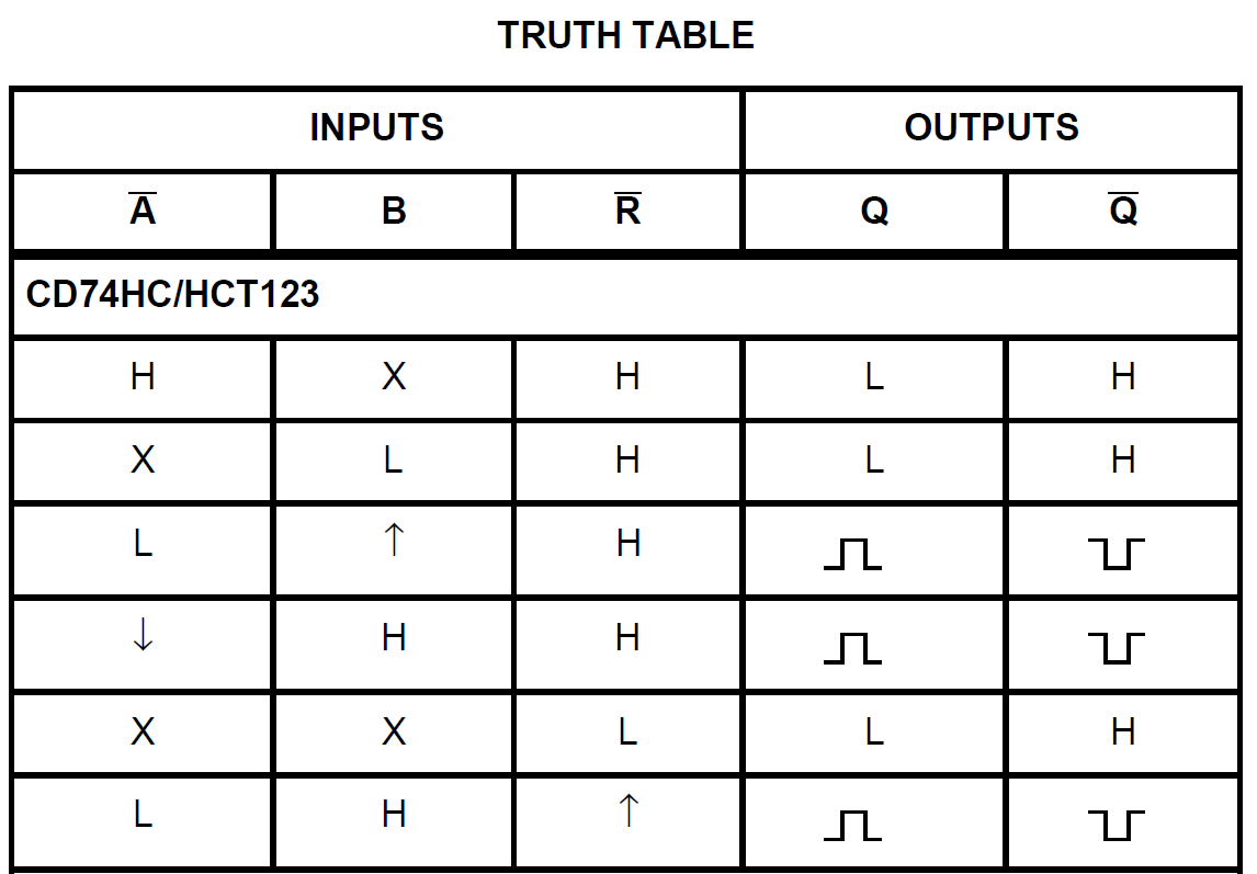
The 74HCT123 (truth table is shown below) is one such integrated circuit – a retriggerable monostable multivibrator. It's available for many logic families (e.g., 74LS123). The output pulse width is set with andan external capacitor and resistor. The caps can be large, but for some logic families, large electrolytic caps might require a diode.

enter image description here

Note that there are many modes in which you can use this integrated circuit, and three of them produce timed pulses in response to rising or falling edges (i.e., the rows with up or down arrows).

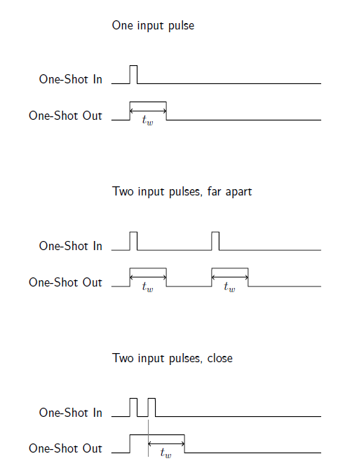
“Retriggerable” means that the output of the integrated circuit will remain high so long as the input sees triggers before the output returns to a low value. As you can see from the example timing diagrams that follow, after a rising edge on the input, the one-shot produces an output pulse and then goes low tw after the input rising edge (if the inputs are so configured), unless before time tw another rising edge is provided, in which case the output stays high until tw following the last rising edge. enter image description here
So, you just put your PWM signal in to the one-shot, with the width set longer than the PWM period, and you generate a signal that stays high until the PWM is over. You send that through a simple inverter. In fact, you don't need the inverter, as there is a \$\bar{Q}\$ output on the chip already.

You need a retriggerable one shot followed by an inverter.

The 74HCT123 (truth table is shown below) is one such integrated circuit – a retriggerable monostable multivibrator. It's available for many logic families (e.g., 74LS123). The output pulse width is set with and external capacitor and resistor. The caps can be large, but for some logic families, large electrolytic caps might require a diode.

enter image description here

Note that there are many modes in which you can use this integrated circuit, and three of them produce timed pulses in response to rising or falling edges (i.e., the rows with up or down arrows).

“Retriggerable” means that the output of the integrated circuit will remain high so long as the input sees triggers before the output returns to a low value. As you can see from the example timing diagrams that follow, after a rising edge on the input, the one-shot produces an output pulse and then goes low tw after the input rising edge (if the inputs are so configured), unless before time tw another rising edge is provided, in which case the output stays high until tw following the last rising edge. enter image description here

So, you just put your PWM signal in to the one-shot, with the width set longer than the PWM period, and you generate a signal that stays high until the PWM is over. You send that through a simple inverter. In fact, you don't need the inverter, as there is a \$\bar{Q}\$ output on the chip already.

You need a retriggerable one shot followed by an inverter.

The 74HCT123 (truth table is shown below) is one such integrated circuit – a retriggerable monostable multivibrator. It's available for many logic families (e.g., 74LS123). The output pulse width is set with an external capacitor and resistor. The caps can be large, but for some logic families, large electrolytic caps might require a diode.

enter image description here

Note that there are many modes in which you can use this integrated circuit, and three of them produce timed pulses in response to rising or falling edges (i.e., the rows with up or down arrows).

“Retriggerable” means that the output of the integrated circuit will remain high so long as the input sees triggers before the output returns to a low value. As you can see from the example timing diagrams that follow, after a rising edge on the input, the one-shot produces an output pulse and then goes low tw after the input rising edge (if the inputs are so configured), unless before time tw another rising edge is provided, in which case the output stays high until tw following the last rising edge. enter image description here

So, you just put your PWM signal in to the one-shot, with the width set longer than the PWM period, and you generate a signal that stays high until the PWM is over. You send that through a simple inverter. In fact, you don't need the inverter, as there is a \$\bar{Q}\$ output on the chip already.

added 93 characters in body
Source Link
Scott Seidman
  • 30.6k
  • 4
  • 46
  • 114

You need a retriggerable one shot followed by an inverter.

The 74HCT123 (truth table is shown below) is one such integrated circuit – a retriggerable monostable multivibrator. It's available for many logic families (e.g., 74LS123). The output pulse width is set with and external capacitor and resistor. The caps can be large, but for some logic families, large electrolytic caps might require a diode.

enter image description here

Note that there are many modes in which you can use this integrated circuit, and three of them produce timed pulses in response to rising or falling edges (i.e., the rows with up or down arrows).

“Retriggerable” means that the output of the integrated circuit will remain high so long as the input sees triggers before the output returns to a low value. As you can see from the example timing diagrams that follow, after a rising edge on the input, the one-shot produces an output pulse and then goes low tw after the input rising edge (if the inputs are so configured), unless before time tw another rising edge is provided, in which case the output stays high until tw following the last rising edge. enter image description here

So, you just put your PWM signal in to the one-shot, with the width set longer than the PWM period, and you generate a signal that stays high until the PWM is over. You send that through a simple inverter. In fact, you don't need the inverter, as there is a \$\bar{Q}\$ output on the chip already.

You need a retriggerable one shot followed by an inverter.

The 74HCT123 (truth table is shown below) is one such integrated circuit – a retriggerable monostable multivibrator. It's available for many logic families (e.g., 74LS123). The output pulse width is set with and external capacitor and resistor. The caps can be large, but for some logic families, large electrolytic caps might require a diode.

enter image description here

Note that there are many modes in which you can use this integrated circuit, and three of them produce timed pulses in response to rising or falling edges (i.e., the rows with up or down arrows).

“Retriggerable” means that the output of the integrated circuit will remain high so long as the input sees triggers before the output returns to a low value. As you can see from the example timing diagrams that follow, after a rising edge on the input, the one-shot produces an output pulse and then goes low tw after the input rising edge (if the inputs are so configured), unless before time tw another rising edge is provided, in which case the output stays high until tw following the last rising edge. enter image description here

So, you just put your PWM signal in to the one-shot, with the width set longer than the PWM period, and you generate a signal that stays high until the PWM is over. You send that through a simple inverter.

You need a retriggerable one shot followed by an inverter.

The 74HCT123 (truth table is shown below) is one such integrated circuit – a retriggerable monostable multivibrator. It's available for many logic families (e.g., 74LS123). The output pulse width is set with and external capacitor and resistor. The caps can be large, but for some logic families, large electrolytic caps might require a diode.

enter image description here

Note that there are many modes in which you can use this integrated circuit, and three of them produce timed pulses in response to rising or falling edges (i.e., the rows with up or down arrows).

“Retriggerable” means that the output of the integrated circuit will remain high so long as the input sees triggers before the output returns to a low value. As you can see from the example timing diagrams that follow, after a rising edge on the input, the one-shot produces an output pulse and then goes low tw after the input rising edge (if the inputs are so configured), unless before time tw another rising edge is provided, in which case the output stays high until tw following the last rising edge. enter image description here

So, you just put your PWM signal in to the one-shot, with the width set longer than the PWM period, and you generate a signal that stays high until the PWM is over. You send that through a simple inverter. In fact, you don't need the inverter, as there is a \$\bar{Q}\$ output on the chip already.

added 173 characters in body
Source Link
Scott Seidman
  • 30.6k
  • 4
  • 46
  • 114

You need a retriggerable one shot followed by an inverter.

The 74HCT123 (truth table is shown below) is one such integrated circuit – a retriggerable monostable multivibrator. It's available for many logic families (e.g., 74LS123). The output pulse width is set with and external capacitor and resistor. The caps can be large, but for some logic families, large electrolytic caps might require a diode.

enter image description here

Note that there are many modes in which you can use this integrated circuit, and three of them produce timed pulses in response to rising or falling edges (i.e., the rows with up or down arrows).

“Retriggerable” means that the output of the integrated circuit will remain high so long as the input sees triggers before the output returns to a low value. As you can see from the example timing diagrams that follow, after a rising edge on the input, the one-shot produces an output pulse and then goes low tw after the input rising edge (if the inputs are so configured), unless before time tw another rising edge is provided, in which case the output stays high until tw following the last rising edge. enter image description here

So, you just put your PWM signal in to the one-shot, with the width set longer than the PWM period, and you generate a signal that stays high until the PWM is over. You send that through a simple inverter.

You need a retriggerable one shot followed by an inverter.

The 74HCT123 (truth table is shown below) is one such integrated circuit – a retriggerable monostable multivibrator. It's available for many logic families (e.g., 74LS123).

enter image description here

Note that there are many modes in which you can use this integrated circuit, and three of them produce timed pulses in response to rising or falling edges (i.e., the rows with up or down arrows).

“Retriggerable” means that the output of the integrated circuit will remain high so long as the input sees triggers before the output returns to a low value. As you can see from the example timing diagrams that follow, after a rising edge on the input, the one-shot produces an output pulse and then goes low tw after the input rising edge (if the inputs are so configured), unless before time tw another rising edge is provided, in which case the output stays high until tw following the last rising edge. enter image description here

So, you just put your PWM signal in to the one-shot, with the width set longer than the PWM period, and you generate a signal that stays high until the PWM is over. You send that through a simple inverter.

You need a retriggerable one shot followed by an inverter.

The 74HCT123 (truth table is shown below) is one such integrated circuit – a retriggerable monostable multivibrator. It's available for many logic families (e.g., 74LS123). The output pulse width is set with and external capacitor and resistor. The caps can be large, but for some logic families, large electrolytic caps might require a diode.

enter image description here

Note that there are many modes in which you can use this integrated circuit, and three of them produce timed pulses in response to rising or falling edges (i.e., the rows with up or down arrows).

“Retriggerable” means that the output of the integrated circuit will remain high so long as the input sees triggers before the output returns to a low value. As you can see from the example timing diagrams that follow, after a rising edge on the input, the one-shot produces an output pulse and then goes low tw after the input rising edge (if the inputs are so configured), unless before time tw another rising edge is provided, in which case the output stays high until tw following the last rising edge. enter image description here

So, you just put your PWM signal in to the one-shot, with the width set longer than the PWM period, and you generate a signal that stays high until the PWM is over. You send that through a simple inverter.

added 1282 characters in body
Source Link
Scott Seidman
  • 30.6k
  • 4
  • 46
  • 114
Loading
Source Link
Scott Seidman
  • 30.6k
  • 4
  • 46
  • 114
Loading