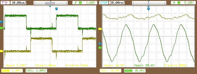
I want to use this [Half Bridge Driver][1]Half Bridge Driver for a Buck converter Design. To validate it, I wire the connection as the simplified application diagram in the datasheet, with .1 uF capacitors. The input VDD is 12V. I feed the High and Low inputs with a %50 percent fixed duty cycle at a 15KHz frequency using a micro-controller as shown below on the Left. There was a small dead-band included for protection.
I expect the output at HO and LO without anything connected to be a square wave but I receive the output below on the right, where green is the low side, and yellow is the high side: [![enter image description here][2]][2]
What did I do wrong? What Can I check? When I turn the driver on without input I see a biased Voltage around 10V. [1]: http://www.ti.com/product/UCC27201/datasheet [2]: https://i.sstatic.net/ViBFI.png
