schematic correction
Source Link
Rohat Kılıç
  • 38.5k
  • 3
  • 32
  • 92

I expect the output at HO and LO without anything connected to be a square wave

Don't.

The MOSFETS need to be connected to see an output square wave? ... Do I also need to connect the inductor and capacitor?

Of course! High side MOSFET needs a gate voltage higher than its source voltage to turn on. As can be seen from the schematic below, the voltage on its source is approximately the output voltage and CBS is used for "adding" this output voltage to the gate. That's called bootstrapping.

Here's how a bootstrapped driver is used in a sync-buck converter:
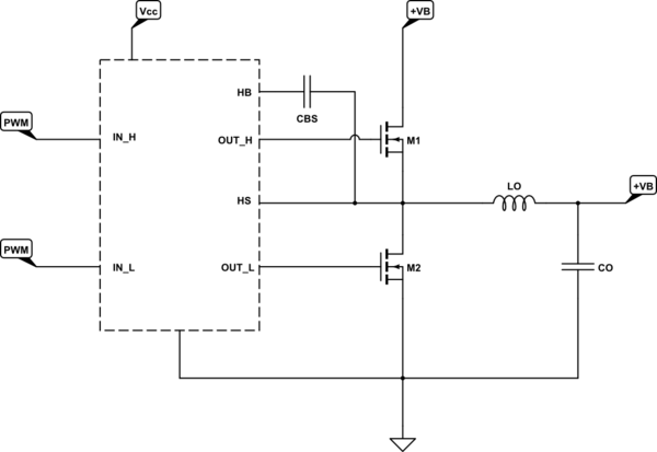
schematicschematic

simulate this circuitsimulate this circuit – Schematic created using CircuitLab

NOTE: I didn't show the external diode because UCC27201 has it internally.

I expect the output at HO and LO without anything connected to be a square wave

Don't.

The MOSFETS need to be connected to see an output square wave? ... Do I also need to connect the inductor and capacitor?

Of course!

Here's how a bootstrapped driver is used in a sync-buck converter:

schematic

simulate this circuit – Schematic created using CircuitLab

NOTE: I didn't show the external diode because UCC27201 has it internally.

I expect the output at HO and LO without anything connected to be a square wave

Don't.

The MOSFETS need to be connected to see an output square wave? ... Do I also need to connect the inductor and capacitor?

Of course! High side MOSFET needs a gate voltage higher than its source voltage to turn on. As can be seen from the schematic below, the voltage on its source is approximately the output voltage and CBS is used for "adding" this output voltage to the gate. That's called bootstrapping.

Here's how a bootstrapped driver is used in a sync-buck converter:
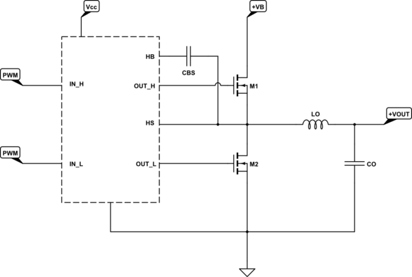
schematic

simulate this circuit – Schematic created using CircuitLab

NOTE: I didn't show the external diode because UCC27201 has it internally.

Source Link
Rohat Kılıç
  • 38.5k
  • 3
  • 32
  • 92

I expect the output at HO and LO without anything connected to be a square wave

Don't.

The MOSFETS need to be connected to see an output square wave? ... Do I also need to connect the inductor and capacitor?

Of course!

Here's how a bootstrapped driver is used in a sync-buck converter:

schematic

simulate this circuit – Schematic created using CircuitLab

NOTE: I didn't show the external diode because UCC27201 has it internally.